 Hyundai Veloster: Smart key unit. Components and Components Location
Hyundai Veloster 2011-2017 Service Manual / Body Electrical System / Smart key System / Smart key unit. Components and Components Location
Hyundai Veloster: Smart key unit. Components and Components Location
Hyundai Veloster 2011-2017 Service Manual / Body Electrical System / Smart key System / Smart key unit. Components and Components Location
Hyundai Veloster 2011-2017 Service Manual / Body Electrical System / Smart key System / Smart key unit. Components and Components Location
Component (1)
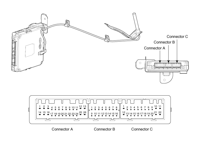
Connector Pin Information
|
No. |
Connector A(26 pins) |
No. |
Connector B(16 pins) |
No. |
Connector C(22 pins) |
|
1 |
Battery power load |
1 |
CAN L |
1 |
Start/Stop button switch ILL |
|
2 |
- |
2 |
CAN H |
2 |
Immobilizer IND |
|
3 |
Power ground 1 |
3 |
- |
3 |
Start/Stop button LED OFF |
|
4 |
IGN 1 |
4 |
Stop lamp fuse |
4 |
Interior antenna #2 power |
|
5 |
IGN 1 relay |
5 |
Brake switch |
5 |
Interior antenna #1 power |
|
6 |
ACC |
6 |
Immobilizer antenna power |
6 |
- |
|
7 |
IGN 2 |
7 |
- |
7 |
- |
|
8 |
Start/Stop button switch 2 |
8 |
Wheel speed |
8 |
Trunk antenna power |
|
9 |
- |
9 |
Driver toggle button |
9 |
Bumper antenna power |
|
10 |
- |
10 |
- |
10 |
Assistant antenna power |
|
11 |
ESCL COM |
11 |
External buzzer |
11 |
Driver antenna power |
|
12 |
CAN H |
12 |
P position / Clutch switch |
12 |
SSB LED IGN |
|
13 |
CAN L |
13 |
Start feedback |
13 |
SSB illumination power |
|
14 |
Battery CPU |
14 |
Immobilizer antenna ground |
14 |
- |
|
15 |
- |
15 |
Diagnostic - K |
15 |
Interior antenna #2 ground |
|
16 |
Power ground 2 |
16 |
Start/Stop button switch LED |
16 |
Interior antenna #1 ground |
|
17 |
Starter relay |
|
|
17 |
- |
|
18 |
IGN 2 relay |
18 |
- |
||
|
19 |
ACC relay |
19 |
Trunk antenna ground |
||
|
20 |
- |
20 |
Bumper antenna ground |
||
|
21 |
Trunk lid switch |
21 |
Assistant antenna ground |
||
|
22 |
- |
22 |
Driver antenna ground |
||
|
23 |
RPM |
|
|
||
|
24 |
EMS COM |
||||
|
25 |
Start/Stop button switch 1 |
||||
|
26 |
Assistant toggle button |
 Smart key. Repair procedures
Smart Key
Smart Key Code Saving
1.
Connect the DLC cable of GDS to the data link connector in driver
side crash pad lower panel, turn the power on GDS.
...
 Smart key unit. Schematic Diagrams
Circuit Diagram
...
See also:
Rear Seat. Repair procedures
Replacement
Rear Seat Assembly Replacement
1.
After loosening the mounting bolts, then remove the
rear seat cushion (A).
Tightening torque ...
Instrument panel illumination
Press the illumination control switch to adjust the instrument panel illumination
intensity. For instrument cluster type A, the vehicle’s parking lights or headlights
should be on to adjust th ...
Rear Glass Defogger Printed Heater. Repair procedures
Inspection
Wrap tin foil around the end of the voltmeter test lead to prevent
damaging the heater line. Apply finger pressure ...
Categories
- Hyundai Veloster Manuals Home
- Hyundai Veloster 2010-2017 Owner's Manual
- Hyundai Veloster 2010-2017 Service Manual

© 2011-2026 Copyright www.hvmanual.com