 Hyundai Veloster: Speakers. Repair procedures
Hyundai Veloster 2011-2017 Service Manual / Body Electrical System / AVN System / Speakers. Repair procedures
Hyundai Veloster 2011-2017 Service Manual / Body Electrical System / AVN System / Speakers. Repair procedures
Inspection
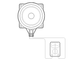
| 1. |
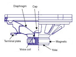
Troubleshooting for Speaker
|
Removal
Front Speaker
| 1. |
Remove the front door trim panel and speaker connector.
(Refer to the BD group - "Front door")
|
| 2. |
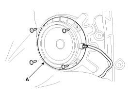
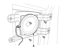
Remove the front speaker (A) after loosening 4 rivets.
|
Rear Speaker (Right)
| 1. |
Remove the rear door trim panel and speaker connector.
(Refer to the BD group - "Interior trim")
|
| 2. |
Remove the rear speaker (A) after removing 4 rivets.
|
Rear Speaker (Left)
| 1. |
Remove the rear door trim panel and speaker connector.
(Refer to the BD group - "Interior trim")
|
| 2. |
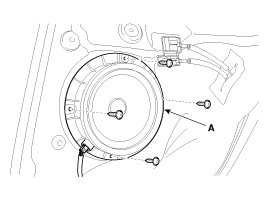
Remove the rear speaker (A) after removing 4 bolts.
|
Center Speaker
| 1. |
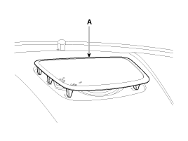
Remove the crash pad upper speaker cover (A).
|
| 2. |
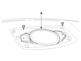
Disconnect the connector, after loosening 2 screws then remove
the center speaker (A).
|
Midrange Speaker
| 1. |
Remove the front door trim panel and speaker connector.
(Refer to the BD group - "Front door")
|
| 2. |
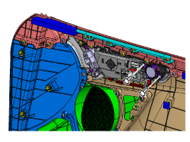
Remove the front midrange speaker, after loosening 2 screws.
|
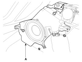
Subwoofer Speaker
| 1. |
Remove the rear fillar trim panel and speaker connector.
(Refer to the BD group - "Interior trim")
|
| 2. |
Remove the subwoofer speaker (A), after loosening 2 bolts and
2 nuts.
|
Installation
Front Speaker
| 1. |
Install the front speaker.
|
| 2. |
Insatll the rivets and connect the connector.
|
| 3. |
Install the front door trim panel.
|
Rear Speaker (Right)
| 1. |
Install the rear speaker.
|
| 2. |
Install the rivets and connect the connector.
|
| 3. |
Install the door trim panel.
|
Rear Speaker (Left)
| 1. |
Install the rear speaker after connecting the connector.
|
| 2. |
Install the door trim panel.
|
Center Speaker
| 1. |
Install the center speaker after connecting the connector.
|
| 2. |
Install the center speaker cover.
|
Mindrange Speaker
| 1. |
Install the midrange speaker after connecting the connector.
|
| 2. |
Install the front door trim panel.
|
Subwoofer Speaker
| 1. |
Install the subwoofer speaker after connecting the connector.
|
| 2. |
Install the rear fillar trim panel.
|
 AVN Head Unit. Repair procedures
Removal
AVN Head Unit
•
Take care not to scratch the center fascia panel and related
par ...
 Antenna. Repair procedures
Inspection
Glass Antenna Test
1.
Wrap aluminum foil (A) around the tip of the tester probe (B)
as shown.
2.
Touch one tester p ...
See also:
Passenger Airbag (PAB) Module. Components and Components Location
Components
...
Seat Belt Pretensioner (BPT). Repair procedures
Removal
1.
Disconnect the battery negative cable, and wait for at least three
minutes before beginning work.
2.
Remove the seat belt afte ...
Variable Intake Solenoid (VIS) Valve. Schematic Diagrams
Circuit Diagram
...
Categories
- Hyundai Veloster Manuals Home
- Hyundai Veloster 2010-2017 Owner's Manual
- Hyundai Veloster 2010-2017 Service Manual
© 2011-2025 Copyright www.hvmanual.com

