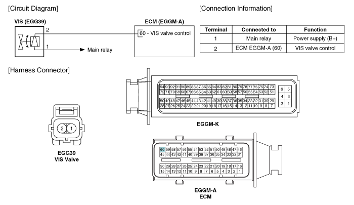
 Hyundai Veloster: Variable Intake Solenoid (VIS) Valve. Schematic Diagrams
Hyundai Veloster 2011-2017 Service Manual / Fuel System / Engine Control System / Variable Intake Solenoid (VIS) Valve. Schematic Diagrams
Hyundai Veloster 2011-2017 Service Manual / Fuel System / Engine Control System / Variable Intake Solenoid (VIS) Valve. Schematic Diagrams
Circuit Diagram

 Variable Intake Solenoid (VIS) Valve. Specifications
Specification
Item
Specification
Coil resistance (Ω)
30.0 ~ 35.0 [20°C(68°F)]
...
 Variable Intake Solenoid (VIS) Valve. Repair procedures
Inspection
1.
Turn the ignition switch OFF.
2.
Disconnect the VIS valve connector.
3.
Measure resistance betwe ...
See also:
Identification Number Locations
...
Electrical System
1.
Be sure to disconnect the battery cable from the negative (-)
terminal of the battery.
2.
Never pull on the wires when disconnecting con ...
Seat Heater. Schematic Diagrams
Circuit Diagram
...
Categories
- Hyundai Veloster Manuals Home
- Hyundai Veloster 2010-2017 Owner's Manual
- Hyundai Veloster 2010-2017 Service Manual
© 2011-2026 Copyright www.hvmanual.com
