
 Hyundai Veloster: Rear Torsion Beam Axle. Repair procedures
Hyundai Veloster 2011-2017 Service Manual / Suspension System / Rear Suspension System / Rear Torsion Beam Axle. Repair procedures
Hyundai Veloster: Rear Torsion Beam Axle. Repair procedures
Hyundai Veloster 2011-2017 Service Manual / Suspension System / Rear Suspension System / Rear Torsion Beam Axle. Repair procedures
Hyundai Veloster 2011-2017 Service Manual / Suspension System / Rear Suspension System / Rear Torsion Beam Axle. Repair procedures
Replacement
| 1. |
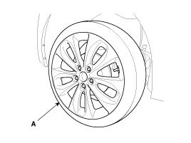
Remove the rear wheel & tire.
|

| 2. |
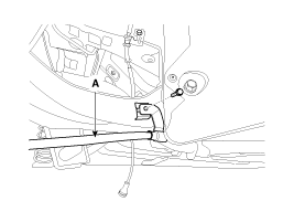
Remove the parking brake bracket (A).
|
| 3. |
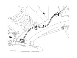
Loosen the bolt and then remove the wheel speed sensor cable (A)
from the torsion beam axle.
|
| 4. |
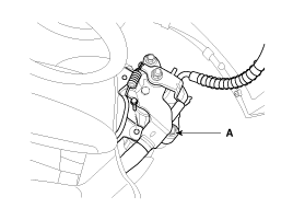
Remove the brake caliper assembly (A) from the torsion beam axle
by loosening the bolts.
|
| 5. |
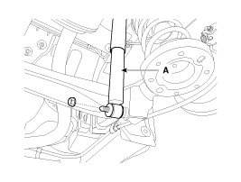
Loosen the bolt & nut and then remove the rear shock absorber
(A) from the torsion beam axle (B).
|
| 6. |
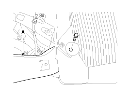
Remove the torsion beam axle (A) from the body loosening the bolts.
|
| 7. |
Remove the rear hub assembly.
(Refer to DS group - "Rear Axle")
|
| 8. |
Installation is the reverse of removal.
|
 Rear Torsion Beam Axle. Components and Components Location
Components
1. Rear torsion beam axle
...
 Tires/Wheels
...
See also:
Luggage net (holder)
To keep items from shifting in the cargo area, you can use the holders located
in the cargo area to attach the luggage net.
CAUTION
To prevent damage to the goods or the vehicle, care should be ...
Engine compartment
1. Engine oil filler cap 2. Engine oil dipstick 3. Brake/clutch fluid reservoir
4. Positive battery terminal 5. Negative battery terminal 6. Fuse box 7. Air
cleaner 8. Radiator cap 9. Engine coo ...
Passenger Airbag (PAB) Module. Components and Components Location
Components
...
Categories
- Hyundai Veloster Manuals Home
- Hyundai Veloster 2010-2017 Owner's Manual
- Hyundai Veloster 2010-2017 Service Manual

В© 2011-2026 Copyright www.hvmanual.com