 Hyundai Veloster: General Information
Hyundai Veloster 2011-2017 Service Manual / Body (Interior and Exterior) / Body Dimensions / General Information
Hyundai Veloster 2011-2017 Service Manual / Body (Interior and Exterior) / Body Dimensions / General Information
General
| 1. |
Basically, all measurements in this manual are taken
with a tracking gauge.
|
| 2. |
When a measuring tape is used, check to be sure there
is no elongation, twisting or bending.
|
| 3. |
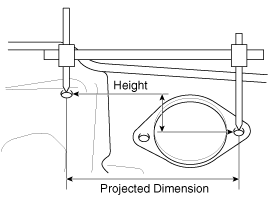
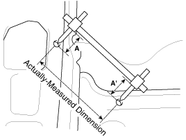
For measuring dimensions, both projected dimension
and actual-measurement dimension are used in this manual.
|
Measurement Method
| Projected Dimensions |
| 1. |
These are the dimensions measured when the measurement
points are projected into the reference plane, and are the reference
dimensions used for body alterations.
|
| 2. |
If the length of the tracking gauge probes is adjustable,
make the measurement by lengthening one probe by the amount equivalent
to the difference in height of the two surfaces.
|
| Actual-Measurement Dimensions |
| 1. |
These dimensions indicate the actual linear distance
between measurement points, and are the reference dimensions for use
if a tracking gauge is used for measurement.
|
| 2. |
Measure by first adjusting both probes to the same
length (A=A').
|
| Measurement Point |
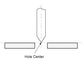
| 1. |
Measurements should be taken at the hole center.
|
 Body Dimensions
...
 Front Body. Body Repair
Front Body A
Hood hinge mounting hole (Ø10)
Fender apron upper member corner
Front shock ...
See also:
Dimensions Projected
1.
These are the dimensions measured when the measurement points
are projected from the vehicle's surface, and are the reference dimensions
used for used for body ...
Schematic Diagrams
Circuit Diagram (1)
Circuit Diagram (2)
...
Fuel Tank Air Filter. Repair procedures
Removal
1.
Turn the ignition switch OFF and disconnect the battery negative
(-) cable.
2.
Lift the vehicle.
3.
...
Categories
- Hyundai Veloster Manuals Home
- Hyundai Veloster 2010-2017 Owner's Manual
- Hyundai Veloster 2010-2017 Service Manual
В© 2011-2025 Copyright www.hvmanual.com


