 Hyundai Veloster: Front Hub / Knuckle. Repair procedures
Hyundai Veloster 2011-2017 Service Manual / Driveshaft and axle / Front Axle Assembly / Front Hub / Knuckle. Repair procedures
Replacement
| 1. |
Loosen the wheel nuts slightly.
Raise the vehicle, and make sure it is securely supported.
|
| 2. |
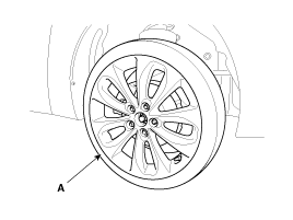
Remove the front wheel and tire (A) from front hub
.
|
| 3. |
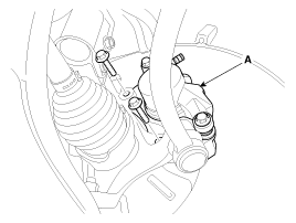
Remove the brake caliper mounting bolts , and then
hold the brake caliper assembly (A) with wire.
|
| 4. |
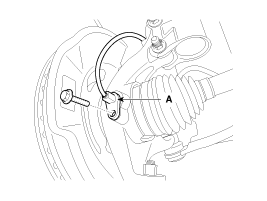
Remove the wheel speed sensor (A).
|
| 5. |
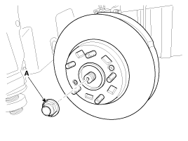
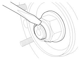
Remove driveshaft caulking nut (A) from the front
hub under applying the brake.
|
| 6. |
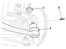
Remove the tie rod end ball joint (A) from the knuckle.
|
| 7. |
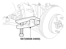
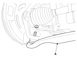
Remove the lower arm (A) from the knuckle by using
SST (09568-34000)
|
| 8. |
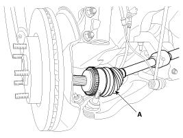
Disconnect the driveshaft (A) from the front hub
assembly.
|
| 9. |
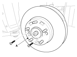
Remove the disc (A) by loosening the screw.
|
| 10. |
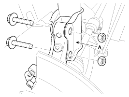
Loosen the strut mounting bolts and then remove the
knuckle assembly (A).
|
| 11. |
Install in the reverse order of removal.
|
Disassembly
| 1. |
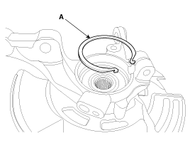
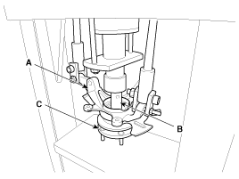
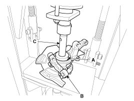
Remove the snap ring (A).
|
| 2. |
Remove the hub assembly from the knuckle assembly.
|
| 3. |
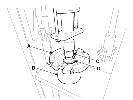
Remove the hub bearing inner race from the hub assembly.
|
| 4. |
Remove the hub bearing outer race from the knuckle
assembly.
|
| 5. |
Replace hub bearing with a new one.
|
Reassembly
| 1. |
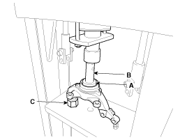
Install the hub bearing to the knuckle assembly.
|
| 2. |
Install the hub assembly to the knuckle assembly.
|
| 3. |
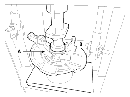
Install the snap ring (A).
|
Inspection
| 1. |
Check the hub for cracks and the splines for wear.
|
| 2. |
Check the brake disc for scoring and damage.
|
| 3. |
Check the knuckle for cracks.
|
 Front Hub / Knuckle. Components and
Components Location
Components
1. Drive shaft caulking nut
2. Brake disc
3. Hub
4. Wheel bearing
6. Snap ring
7. Dust cover
8. Knuckle
9. Drive shaft
...
See also:
Storing and recalling stations
You can easily store up to 12 preset stations for later recall at the touch of
a button.
1. Select the band (FM, AM) you want to store a station into. 2. Select the
desired frequency. 3. Touch [P ...
Front Wheel Speed Sensor. Components and Components Location
Components
1. Front wheel speed sensor
2. Front wheel speed sensor connector
...
Instrument Cluster. Description and Operation
Active ECO System
1.
Active ECO System
While the general eco system encourages the driver to drive efficiently
by displaying ECO lights on the dashboard, the activ ...
Categories
- Hyundai Veloster Manuals Home
- Hyundai Veloster 2010-2017 Owner's Manual
- Hyundai Veloster 2010-2017 Service Manual

