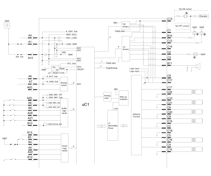
 Hyundai Veloster: Smart key unit. Schematic Diagrams
Hyundai Veloster 2011-2017 Service Manual / Body Electrical System / Smart key System / Smart key unit. Schematic Diagrams
Hyundai Veloster 2011-2017 Service Manual / Body Electrical System / Smart key System / Smart key unit. Schematic Diagrams
Circuit Diagram


 Smart key unit. Components and Components Location
Component (1)
Connector Pin Information
No.
Connector A(26 pins)
No.
Connector B(16 pins)
No.
Connector C(22 pins)
...
 Smart key unit. Repair procedures
Inspection
Smart Key Unit
-
Refer to the BE group - inspection / self diagnosis with GDS.
Smart Key Switch
-
Refer to the BE group - inspecti ...
See also:
Accelerator Position Sensor (APS). Description and Operation
Description
Accelerator Position Sensor (APS) is installed on the accelerator pedal
module and detects the rotation angle of the accelerator pedal. The APS is one
of the most important senso ...
Vehicle break-in process
No special break-in period is needed. By following a few simple precautions for
the first 600 miles (1,000 km) you may add to the performance, economy and life
of your vehicle.
Do not race the ...
Description and Operation
Description of ESC
Optimum driving safety now has a name : ESC, the Electronic Stability
Control.
ESC recognizes critical driving conditions, such as panic reactions in
dangerous sit ...
Categories
- Hyundai Veloster Manuals Home
- Hyundai Veloster 2010-2017 Owner's Manual
- Hyundai Veloster 2010-2017 Service Manual
В© 2011-2026 Copyright www.hvmanual.com
