 Hyundai Veloster: Inhibitor Switch > Repair procedures
Hyundai Veloster 2011-2017 Service Manual / Dual Clutch Transmission(DCT) System / Dual Clutch Transmission Control System / Inhibitor Switch > Repair procedures
Hyundai Veloster 2011-2017 Service Manual / Dual Clutch Transmission(DCT) System / Dual Clutch Transmission Control System / Inhibitor Switch > Repair procedures
Inspection
| 1. |
Inspect for loosened connectors, faulty connections, bends, corrosion,
contamination, deformation, or damage.
|
| 2. |
Disconnect the inhibitor switch connector.
|
| 3. |
Check the voltage on the power supply terminal and the ground
of the inhibitor switch wiring.
|
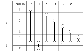
| 4. |
Use the following signal code chart to check the electric current
flow for each terminal in each gear.
|
Removal
| 1. |
Remove the following parts first:
|
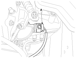
| 2. |
Disconnect the inhibitor switch connector (A).
|
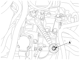
| 3. |
Remove the shift cable mounting nut (A).
|
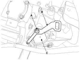
| 4. |
Loosen the nut (A), and then remove the manual control lever (B).
|
| 5. |
Loosen the mounting bolt, and then remove the inhibitor switch
(C).
|
Installation
| 1. |
Installation is the reverse of removal.
|
 Inhibitor Switch > Description and Operation
Description
The inhibitor switch is mounted on the transmission case. It includes
the electric switch plate circuit and is directly connected with the transmission
lever via transmission cab ...
 Shift Lever > Components and Components Location
Components
1. Shift lever knob
2. Shift lever assembly
3. Control cable assembly
...
See also:
Rear Washer Motor. Repair procedures
Inspection
1.
With the washer motor connected to the reservoir tank, fill the
reservoir tank with water.
...
Notes on the safe use of the Tire Mobility Kit
Park your car at the side of the road so that you can work with the Tire
Mobility Kit away from moving traffic. Place your warning triangle in a prominent
place to make passing vehicles aware ...
Passenger Airbag (PAB) Module. Components and Components Location
Components
...
Categories
- Hyundai Veloster Manuals Home
- Hyundai Veloster 2010-2017 Owner's Manual
- Hyundai Veloster 2010-2017 Service Manual
© 2011-2025 Copyright www.hvmanual.com


