 Hyundai Veloster: Variable Intake Solenoid (VIS) Valve. Repair procedures
Hyundai Veloster 2011-2017 Service Manual / Fuel System / Engine Control System / Variable Intake Solenoid (VIS) Valve. Repair procedures
Hyundai Veloster 2011-2017 Service Manual / Fuel System / Engine Control System / Variable Intake Solenoid (VIS) Valve. Repair procedures
Inspection
| 1. |
Turn the ignition switch OFF.
|
| 2. |
Disconnect the VIS valve connector.
|
| 3. |
Measure resistance between VIS valve terminals 1 and 2.
|
Removal
| 1. |
Turn the ignition switch OFF and disconnect the battery negative
(-) cable.
|
| 2. |
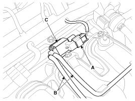
Disconnect the variable intake solenoid valve connector (A).
|
| 3. |
Disconnect the vacuum hoses (B) from the valve.
|
| 4. |
Remove the installation bolt, and then remove the valve (C) from
the surge tank.
|
Installation
|
|
| 1. |
Installation is reverse of removal.
|
 Variable Intake Solenoid (VIS) Valve. Schematic Diagrams
Circuit Diagram
...
 Fuel Pressure Control Valve. Description and Operation
Description
Fuel Pressure Regulator Valve is installed on the high pressure fuel pump
and controls fuel flow flowing into the injectors in accordance with the ECM
signal calculated based on ...
See also:
Manual Transaxle. Repair procedures
Removal
1.
Remove the following items;
A.
Engine cover (A).
(Refer to "Intake and Exhaust system" in
EM group)
...
Battery Sensor
Description and Operation
Description
Vehicles have many control units that use more electricity. These units
control their own system based on information from diverse sensors. It is importan ...
Components and Components Location
Component Location
1. Hood switch
2. Burglar horn
3. IPM (BCM) and RF antenna
4. Key warning switch
5. Front door switch
6. Front door lock actuator & sw ...
Categories
- Hyundai Veloster Manuals Home
- Hyundai Veloster 2010-2017 Owner's Manual
- Hyundai Veloster 2010-2017 Service Manual
© 2011-2026 Copyright www.hvmanual.com

