 Hyundai Veloster: Manual Transaxle. Repair procedures
Hyundai Veloster 2011-2017 Service Manual / Manual Transaxle System (M6CF1) / Manual Transaxle System / Manual Transaxle. Repair procedures
Hyundai Veloster: Manual Transaxle. Repair procedures
Hyundai Veloster 2011-2017 Service Manual / Manual Transaxle System (M6CF1) / Manual Transaxle System / Manual Transaxle. Repair procedures
Removal
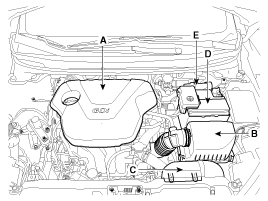
| 1. |
Remove the following items;
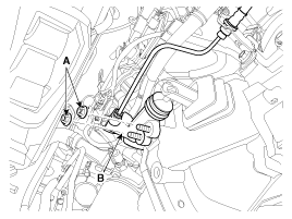
|
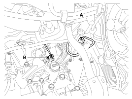
| 2. |
Disconnect the vehicle speed sensor connector (A).
|
| 3. |
Remove the back up lamp switch connector (B).
|
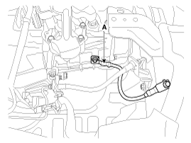
| 4. |
Remove the ground cable from transaxle (A).
|
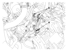
| 5. |
Disconnect the shift cable bracket bolts (B-3ea)
after removing the washer and pin (A).
|
| 6. |
Remove the tube bracket bolt (A).
|
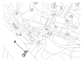
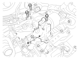
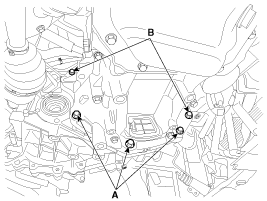
| 7. |
Remove the transaxle upper mounting bolt (B-2ea)
and the start motor mounting bolt (A-2ea).
|
| 8. |
Remove the cowl top cover.
(Refer to "Interior(cowl top cover)" in BD group.)
|
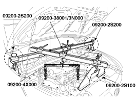
| 9. |
Using the engine support fixture (Support SST No.:
09200-2S100/2S200, Adapter SST No.: 09200-4X000, Beam SST No.: 09200-38001/3N000),
hold the engine and transaxle assembly safely.
|
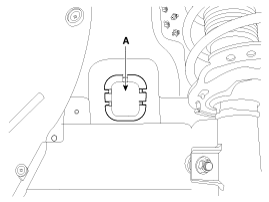
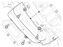
| 10. |
Remove the mounting cover (A).
|
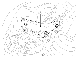
| 11. |
Remove the transaxle support mounting bracket bolts
(A-2ea).
|
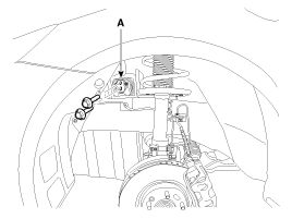
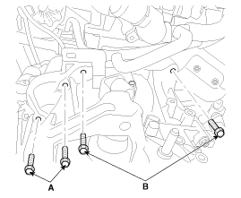
| 12. |
Remove the transaxle support mounting bracket (A).
|
| 13. |
Remove the under cover (A).
|
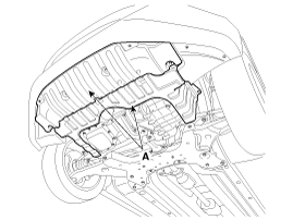
| 14. |
Remove the drive shaft assembly.
(Refer to "Drive shaft assembly" in DS group.)
|
| 15. |
Remove the clutch release cylinder assembly (B) after
removing the nuts (A-2ea).
|
| 16. |
Remove the roll rod support bracket (C) after removing
bolt (A,B).
|
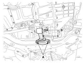
| 17. |
Remove the drive shaft cover (A).
|
| 18. |
Remove the brackets (A).
|
| 19. |
Remove the lower mounting bolts (A-3ea, B-2ea) of
lower part of the transaxle, and remove the transaxle assembly by supporting
it with a jack.
|
Installation
| 1. |
Installation is the reverse of removal.
|
 Manual Transaxle. Components and Components Location
Components
1. Transaxle support bracket
2. Control shaft complete
3. Back up lamp switch
4. Speedmeter
...

See also:
Interior overview
1. Door lock/unlock button 2. Outside rearview mirror control switch 3. Central
door lock switch 4. Power window lock switch 5. Power window switches 6. Hood
release lever 7. Instrument panel il ...
Special Service Tools
Special Service Tools
Tool (Number and name)
Illustration
Use
09411-1P000
Clutch disc guide
Installation of the clu ...
Driver Airbag (DAB) Module and Clock Spring. Description and Operation
Description
Driver Airbag (DAB) is installed in the steering wheel and electrically
connected to SRSCM via the clock spring. It protects the driver by deploying
the airbag when frontal crash ...
Categories
- Hyundai Veloster Manuals Home
- Hyundai Veloster 2010-2017 Owner's Manual
- Hyundai Veloster 2010-2017 Service Manual
