 Hyundai Veloster: Components and Components Location
Hyundai Veloster 2011-2017 Service Manual / Body Electrical System / Multifunction switch / Components and Components Location
Hyundai Veloster 2011-2017 Service Manual / Body Electrical System / Multifunction switch / Components and Components Location
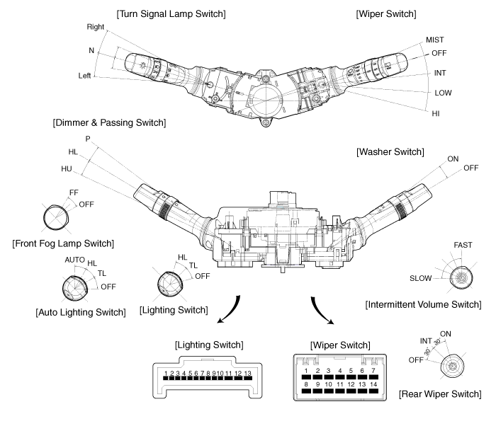
Components(1)

|
Connector name |
No |
Descripton |
Connector name |
No |
RH SIDE |
|
Lighting (13 pin) -LH side |
1 |
Lighting switch ground |
Washer & Wiper (14 pin) -RH side |
1 |
MIST switch |
|
2 |
Tail lamp switch |
2 |
Wiper parking |
||
|
3 |
Auto light switch |
3 |
Wiper low speed |
||
|
4 |
Head lamp switch |
4 |
- |
||
|
5 |
Fog switch base |
5 |
Rear washer switch |
||
|
6 |
Front fog switch |
6 |
IGN2-Rear wiper & washer |
||
|
7 |
- |
7 |
INT rear wiper switch |
||
|
8 |
Head lamp low beam |
8 |
Intermittent wiper switch |
||
|
9 |
Head lamp high beam |
9 |
Wiper high speed |
||
|
10 |
Dimmer switch base |
10 |
ING2-Front washer & wiper |
||
|
11 |
Turn signal left |
11 |
Wahser switch |
||
|
12 |
Turn signal base |
12 |
Intermittent volume base |
||
|
13 |
Turn signal right |
13 |
Intermittent time |
||
|
|
14 |
Rear wiper switch |
|||
 Specifications
Specifications
Items
Specifications
Rated voltage
DC 12V
Operating temperature range
-30°C ~ +80°C (-22 ~ +176°F)
...
 Repair procedures
Inspection
Lighting Switch Inspection
With the multifunction switch in each position, make sure that continuity
exists between the terminals below. If continuity is not as specified, replac ...
See also:
If the engine will not start
If engine doesn't turn over or turns over slowly
1. If your vehicle has an automatic transaxle, be sure the shift lever is in
N (Neutral) or P (Park) and the emergency brake is set. 2. Check th ...
Sunshade
The sunshade will automatically open, when you push the sunroof control lever
backward to the first detent and then release it.
The sunshade will automatically close, when you push the sunroof co ...
Front Strut Assembly. Repair procedures
Replacement
1.
Remove the front wheel & tire.
Tightening torque :
88.3 ~ 107.9N.m(9.0 ~ 11.0kgf.m, 65.1 ~ 79.6lb-ft)
...
Categories
- Hyundai Veloster Manuals Home
- Hyundai Veloster 2010-2017 Owner's Manual
- Hyundai Veloster 2010-2017 Service Manual
© 2011-2026 Copyright www.hvmanual.com
