 Hyundai Veloster: Alignment. Repair procedures
Hyundai Veloster 2011-2017 Service Manual / Suspension System / Tires/Wheels / Alignment. Repair procedures
Front Wheel Alignment
• When using a commercially available computerized wheel alignment
equipment to inspect the front wheel alignment, always position the
vehicle on a level surface with the front wheels facing straight ahead.
• Prior to inspection, make sure that the front suspension and
steering system are in normal operating condition and that the tires
are inflated to the specified pressure.
• You have to ASP (Absolute Steering Position) calibration after
alignment adjusting.
|
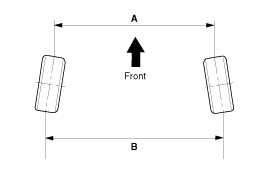
Toe

B - A. 0: Toe in (+)
B - A < 0: Toe out (-)
|
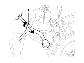
Toe Adjustment
| 1. |
Loosen the tie rod end lock nut.
|
| 2. |
Remove the bellows clip to prevent the bellows from being twisted.
|
| 3. |
Adjust the toe by screwing or unscrewing the tie rod. Toe adjustment
should be made by turning the right and left tie rods by the same amount.
|
| 4. |
When completing the toe adjustment, install the bellows clip and
tighten the tie rod end lock nut to specified torque.
|
Camber and Caster
Camber angle : -0.5° ±
0.5°
|
Caster angle : 4.22° ±
0.5°
|
Rear Wheel Alignment
When using a commercially available computerized wheel alignment
equipment to inspect the rear wheel alignment, always position the vehicle
on a level surface.
Prior to inspection, make sure that the rear suspension system
is in normal operating condition and that the tires are inflated to
the specified pressure.
|
Toe

B - A. 0: Toe in (+)
B - A < 0: Toe out (-)
|
Toe:
Total : 0.5°(+0.5°/ -0.4°)
Individual : 0.25°(+0.25°/ -0.2°)
|
Camber
Camber : -1.5°±0.5°
|
 Tires/Wheels
...
 Wheel. Repair procedures
Hub Nut Tightening Sequence
Tighten the hub nuts as follows.
Tightening torque :
88.3 ~ 107.9N.m (9.0 ~ 11.0kgf.m, 65.1 ~ 79.6lb-ft)
...
See also:
Emergency tailgate safety release
Your vehicle is equipped with the emergency tailgate safety release located on
the bottom of the tailgate. When someone is inadvertently locked in the luggage
compartment, the tailgate can be op ...
Instrument panel fuse replacement
1. Turn the ignition switch and all other switches off. 2. Open the fuse panel
cover.
3. Pull the suspected fuse straight out. Use the removal tool provided in the
engine compartment fuse pan ...
Front Door. Repair procedures
Replacement
Front Door Trim Replacement
•
Take care not to scratch the door trim and
oth ...
Categories
- Hyundai Veloster Manuals Home
- Hyundai Veloster 2010-2017 Owner's Manual
- Hyundai Veloster 2010-2017 Service Manual

