 Hyundai Veloster: Power Door Lock Actuators. Repair procedures
Hyundai Veloster 2011-2017 Service Manual / Body Electrical System / Power Door Locks / Power Door Lock Actuators. Repair procedures
Inspection
| 1. |
Remove the front door trim.
(Refer to the BD group - "Front door")
|
| 2. |
Remove the front door module.
|
| 3. |
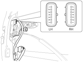
Disconnect the 7P connector from the actuator.
|
| 4. |
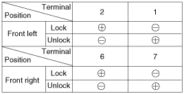
Check actuator operation by connecting power and ground according
to the table. To prevent damage to the actuator, apply battery voltage
only momentarily.
|
| 1. |
Remove the rear door trim.
(Refer to the BD group - "Rear door")
|
| 2. |
Remove the rear door module.
|
| 3. |
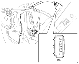
Disconnect the 7P connector from the actuator.
|
| 4. |
Check actuator operation by connecting power and ground according
to the table. To prevent damage to the actuator, apply battery voltage
only momentarily.
|
| 1. |
Remove the tailgate trim panel.
(Refer to the BD group - "Tailgate")
|
| 2. |
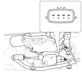
Disconnect the 4P connector from the actuator.
|
| 3. |
Check actuator operation by connecting power and ground according
to the table. To prevent damage to the actuator, apply battery voltage
only momentarily.
|
| 1. |
Remove the front door trim panel.
(Refer to the BD group - "Front door")
|
| 2. |
Remove the front door module.
|
| 3. |
Disconnect the 7P connector from the actuator.
|
| 4. |
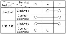
Check for continuity between the terminals in each switch position
when inserting the key into the door according to the table.
|
| 1. |
Remove the rear door trim panel.
(Refer to the BD group - "Rear door")
|
| 2. |
Remove the rear door module.
|
| 3. |
Disconnect the 7P connector from the actuator.
|
| 4. |
Check for continuity between the terminals in each switch position
according to the table.
|
| 1. |
Remove the tailgate trim.
(Refer to the BD group - "Tailgate")
|
| 2. |
Disconnect the 4P connector from the actuator.
|
| 3. |
Check for continuity between the terminals in each switch position
according to the table.
|
 Components and Components Location
Component Location
1. Driver power window switch
2. Door lock switch
3. IPM
4. Front door lock actuator
5. Rear door lock actuator
6. Tailgate open actuator
...
 Power Door Lock Switch. Repair procedures
Inspection
Diagnosis With GDS
1.
It will be able to diagnose defects of power door lock with GDS
quickly. GDS can operates actuator forcefully, input/output value moni ...
See also:
Camshaft Position Sensor (CMPS). Repair procedures
Inspection
1.
Check the signal waveform of the CMPS and CKPS using the GDS.
Specification:
Refer to “Wave Form”
...
Identification Number Description
Vehicle Identification Number
1.
World Manufacturer Identifier (WMI)
A.
KMF : Commercial vehicle (Van)
B.
...
Double clutch transmission operation
The automatic transaxle has 6 forward speeds and one reverse speed. The individual
speeds are selected automatically, depending on the position of the shift lever.
✽ NOTICE
The first few sh ...
Categories
- Hyundai Veloster Manuals Home
- Hyundai Veloster 2010-2017 Owner's Manual
- Hyundai Veloster 2010-2017 Service Manual

