 Hyundai Veloster: Using the Tire Mobility Kit
Hyundai Veloster 2011-2017 Owner's Manual / What to do in an emergency / If you have a flat tire (with tire mobility kit) / Using the Tire Mobility Kit
Hyundai Veloster: Using the Tire Mobility Kit
Hyundai Veloster 2011-2017 Owner's Manual / What to do in an emergency / If you have a flat tire (with tire mobility kit) / Using the Tire Mobility Kit
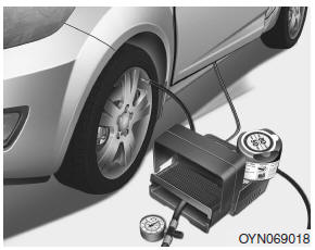
1. Shake the sealant bottle.
2. Screw connection hose (9) onto the connector
of the sealant bottle.
3. Ensure that button (8) on the compressor is not pressed.
4. Unscrew the valve cap of the damaged tire and connect filling hose (2) of the
sealant bottle to the valve.
5. Insert the sealant bottle into the holder (4)
of the compressor so that the bottle is upright.
✽ NOTICE
If a foreign object is seen that has punctured the tire, do not remove it before using Tire Mobility Kit.
6. Ensure that the compressor is switched off, position 0.
7. Connect between
compressor and the vehicle power outlet using the cable and connectors.
8. With
the ignition switched on:
Switch on the compressor and let it run for approximately
3 minutes to fill the sealant. The inflation pressure of the tire after filling
is unimportant.
9. Switch off the compressor.
10. Detach the hoses from the
sealant bottle connector and from the tire valve.
Return the Tire Mobility Kit to its storage location in the vehicle.
WARNING
Carbon monoxide poisoning and suffocation is possible if the engine is left running in a poorly ventilated or unventilated location (such as inside a building).
Distributing the sealant
11. Immediately drive approximately 2 miles (3 km) to evenly distribute the sealant in the tire.
CAUTION
Do not exceed a speed of 35 mph (60 km/h). If possible, do not fall below a speed of 12 mph (20 km/h).
While driving, if you experience any unusual vibration, ride disturbance or noise, reduce your speed and drive with caution until you can safely pull off of the side of the road. Call for road side service or towing.
 Components of the Tire Mobility Kit
0. Speed restriction label 1. Sealant bottle and label with speed restriction
2. Filling hose from sealant bottle to wheel 3. Connectors and cable for the power
outlet direct connection 4. Holde ...
 Setting the tire inflation pressure
12. After driving approximately 2 miles (3 km), stop at a suitable location.
13. Connect connection hose (9) of the compressor directly to the tire valve.
14. Connect between compressor and the ve ...
See also:
Components and Components Location
Component Location (1)
1. Buzzer
2. Smart key unit
3. Interior antenna 1
4. Interior antenna 2
5. Trunk antenna
6. Bumper antenna
Component Locat ...
Schematic Diagrams
System circuit diagram
Connector pin number
Pin No.
Discription
Remark
1
IG ON
...
Driver Airbag (DAB) Module and Clock Spring. Repair procedures
Removal
1.
Disconnect the battery negative cable and wait for at least three
minutes before beginning work.
2.
Turn the steering wheel so ...
Categories
- Hyundai Veloster Manuals Home
- Hyundai Veloster 2010-2017 Owner's Manual
- Hyundai Veloster 2010-2017 Service Manual
