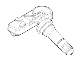
OFF mod
|
| •
|
Air pressure sample : 60 sec
|
| •
|
Temperature sample : 60 sec•
|
| •
|
Exit – LF command or pressure change of. 19 psi
|
|
Stationary mod
|
| •
|
Entry – From OFF mod or when no motion detected
|
| •
|
Air pressure sample : 60 sec
|
| •
|
Temperature sample : 60 sec
|
| •
|
Motion sample : 15sec
|
| •
|
Exit – When detected motion by sensor & verified
|
|
AL (Auto learning) mod
|
| •
|
Entry – Motion detected
|
| •
|
Air pressure sample : 10.8 sec
|
| •
|
Temperature sample : 10.8 sec
|
| •
|
Motion sample : 10.8 sec
|
| •
|
Exit – Transmission of 16 blocks
|
|
Roll mod
|
| •
|
Entry – AL mod expires
|
| •
|
Air pressure sample : 15 sec
|
| •
|
Temperature sample : 15 sec
|
| •
|
Motion sample : 60 sec
|
| •
|
Exit – no further motion detected
|
|
Service mod
|
| •
|
Entry – Speed below detection level
|
| •
|
Air pressure sample : 15 sec
|
| •
|
Temperature sample : 15 sec
|
| •
|
Motion sample : 15 sec
|
| •
|
Exit – Further motion detected
|
|
RF test mod
|
| •
|
Air pressure sample : 15 sec
|
| •
|
Temperature sample : 15 sec
|
| •
|
Motion sample : 15 sec
|
| •
|
Exit – Following 8hrs duration
|
|
Alter mod
|
| •
|
Entry – Detection of pressure change
|
| •
|
Air pressure sample : 2 sec
|
| •
|
Temperature sample : 2 sec
|
| •
|
Exit – Following 2 pressure sample or pressure
|
|
See also:
Schematic Diagrams
Circuit Diagram (1)
Circuit Diagram (2)
SRSCM Connector terminal
Pin
Function (Connector A)
Pin
Function (Connector B)
...
Passive Occupant Detection System (PODS-F). Repair procedures
Removal
PODS-F ECU
1.
Disconnect the battery negative cable, and wait for at least three
minutes before beginning work.
2.
Remove the ...
Front fog light
Fog lights are used to provide improved visibility when visibility is poor due
to fog, rain or snow etc. The fog lights will turn on when fog light switch (1)
is turned to ON after the headlight ...
 Hyundai Veloster: TPMS Sensor. Description and Operation
Hyundai Veloster 2011-2017 Service Manual / Suspension System / Tire Pressure Monitoring System / TPMS Sensor. Description and Operation

 Troubleshooting
 TPMS Sensor. Repair procedures