 Hyundai Veloster: Repair procedures
Hyundai Veloster 2011-2017 Service Manual / Body Electrical System / Ignition Switch Assembly / Repair procedures
Hyundai Veloster: Repair procedures
Hyundai Veloster 2011-2017 Service Manual / Body Electrical System / Ignition Switch Assembly / Repair procedures
Removal
| 1. |
Disconnect the negative (-) battery terminal.
|
| 2. |
Remove the driver crash pad lower panel.
(Refer to the BD group - "Crash pad")
|
| 3. |
Remove the steering column upper and lower shrouds.
(Refer to the BD group - "Crash pad")
|
| 4. |
Remove the wiper switch.
(Refer to the BE group - "Multifunction switch")
|
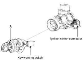
| 5. |
Remove the ignition switch after disconnecting the ignition switch
6P connector.
|
| 6. |
Remove the key warning/immobilizer connector (A).
|
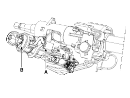
| 7. |
After loosening the screw, remove the key warning switch (B).
|
| 8. |
Pushing lock pin with key ACC.
|
| 9. |
Remove the key lock cylinder (A).
|
Installation
| 1. |
Install the key lock cylinder.
|
| 2. |
Install the key warning switch.
|
| 3. |
Install the key warning/immobilizer connector.
|
| 4. |
Connect the ignition switch connector after Install the ignition
switch.
|
| 5. |
Install the wiper switch.
|
| 6. |
Install the steering column shrouds.
|
| 7. |
Install the driver crash pad lower panel.
|
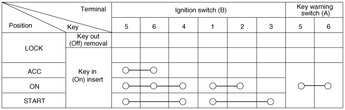
Inspection
| 1. |
Disconnect the ignition switch connector (B) and key warning switch
connector (A) from the steering column.
|
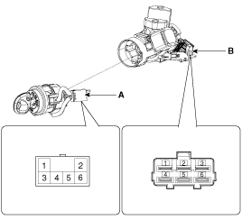
| 2. |
Check for continuity between the terminals.
|
| 3. |
If continuity is not as specified, replace the switch.
|


See also:
Description and Operation
System Overview
RPAS(Rear Parking Assist System) is an electronic driving aid device warning
driver to be cautious during parking or low speed when after detecting an object
on side and behi ...
Additional safety precautions
Never let passengers ride in the cargo area or on top of a foldeddown
back seat. All occupants should sit upright, fully back in their seats with
their seat belts on and their feet on the flo ...
Crankshaft Position Sensor (CKPS). Repair procedures
Inspection
1.
Check signal waveform of CKPS and CMPS using a GDS.
Specification:
Refer to “Waveform”
Re ...
Categories
- Hyundai Veloster Manuals Home
- Hyundai Veloster 2010-2017 Owner's Manual
- Hyundai Veloster 2010-2017 Service Manual
