 Hyundai Veloster: Heated Oxygen Sensor (HO2S). Repair procedures
Hyundai Veloster 2011-2017 Service Manual / Fuel System / Engine Control System / Heated Oxygen Sensor (HO2S). Repair procedures
Hyundai Veloster 2011-2017 Service Manual / Fuel System / Engine Control System / Heated Oxygen Sensor (HO2S). Repair procedures
Inspection
| 1. |
Turn the ignition switch OFF.
|
| 2. |
Disconnect the HO2S connector.
|
| 3. |
Measure resistance between the HO2S terminals 4 and 5 [B1/S1].
|
| 4. |
Measure resistance between the HO2S terminals 3 and 4 [B1/S2].
|
| 5. |
Check that the resistance is within the specification.
|
Removal
| 1. |
Turn the ignition switch OFF and disconnect the battery negative
(-) cable.
|
| 2. |
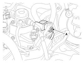
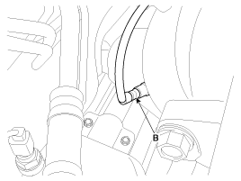
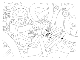
Disconnect the connector (A), and then remove the sensor (B).
[Bank 1 / Sensor 1]
[Bank 1 / Sensor 2]
|
Installation
|
|
| 1. |
Installation is reverse of removal.
|
 Heated Oxygen Sensor (HO2S). Schematic Diagrams
Circuit Diagram
...
 Rail Pressure Sensor (RPS). Description and Operation
Description
Rail Pressure Sensor (RPS) is installed on the delivery pipe and measures
the instantaneous fuel pressure in the delivery pipe. The sensing element (Semiconductor
element) built ...
See also:
Fuel Tank Pressure Sensor (FTPS). Description and Operation
Description
Fuel Tank Pressure Sensor (FTPS) is a component of the evaporative emission
control system and is installed on the fuel tank, the fuel pump, or the canister.
It checks the purge ...
Anchor Pretensioner (APT). Components and Components Location
Components
...
Blade replacement
When the wipers no longer clean adequately, the blades may be worn or cracked,
and require replacement.
CAUTION
To prevent damage to the wiper arms or other components, do not attempt to
move th ...
Categories
- Hyundai Veloster Manuals Home
- Hyundai Veloster 2010-2017 Owner's Manual
- Hyundai Veloster 2010-2017 Service Manual
© 2011-2025 Copyright www.hvmanual.com


