 Hyundai Veloster: Fender. Repair procedures
Hyundai Veloster 2011-2017 Service Manual / Body (Interior and Exterior) / Exterior / Fender. Repair procedures
Hyundai Veloster 2011-2017 Service Manual / Body (Interior and Exterior) / Exterior / Fender. Repair procedures
Replacement
|
| 1. |
Remove the front bumper cover.
(Refer to the BD group – “Front bumper”)
|
| 2. |
Remove the head lamps.
(Refer to the BE group – “Head Lamps”)
|
| 3. |
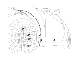
Loosen the mud guard (A) mounting screws and clips.
|
| 4. |
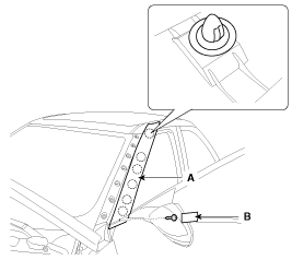
To remove the A pillar garnish (A), loosen the mounting
screw after removing the cap (B).
|
| 5. |
Detach the clip and then remove the fender side cover
(A).
|
| 6. |
Detach the clips and then remove the insulator pad
(A).
|
| 7. |
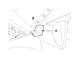
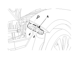
After loosening the mounting screws and bolt, then
remove the front bumper side mounting bracket (A).
|
| 8. |
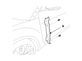
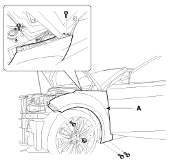
After loosening the mounting bolts and nut, then
remove the fender (A).
|
| 9. |
Installation is the reverse of removal.
|
 Exterior
...
 Hood. Repair procedures
Replacement
Hood Assembly Replacement
•
When removing and installing the hood, an
assis ...
See also:
Indicator symbols on the instrument cluster
...
Components and Components Location
Components
1. Power door mirror
2. Power door mirror switch
...
Immobilizer Control Unit. Repair procedures
Removal
1.
Disconnect the negative (-) battery terminal.
2.
Remove the crash pad lower panel.
(Refer to the BD group - "Crash pad& ...
Categories
- Hyundai Veloster Manuals Home
- Hyundai Veloster 2010-2017 Owner's Manual
- Hyundai Veloster 2010-2017 Service Manual
© 2011-2026 Copyright www.hvmanual.com

