 Hyundai Veloster: Canister Close Valve (CCV). Repair procedures
Hyundai Veloster 2011-2017 Service Manual / Fuel System / Engine Control System / Canister Close Valve (CCV). Repair procedures
Hyundai Veloster 2011-2017 Service Manual / Fuel System / Engine Control System / Canister Close Valve (CCV). Repair procedures
Inspection
| 1. |
Turn the ignition switch OFF.
|
| 2. |
Disconnect the CCV connector.
|
| 3. |
Measure resistance between the CCV terminal 1 and 2.
|
| 4. |
Check that the resistance is within the specification.
|
| 5. |
Disconnect the vapor hose connected with the canister from the
CCV.
|
| 6. |
Connect a vacuum pump to the nipple.
|
| 7. |
Ground the CCV control line and apply battery voltage to the CCV
power supply line.
|
| 8. |
Apply vacuum and check the valve operation.
|
Removal
| 1. |
Turn the ignition switch OFF and disconnect the battery negative
(-) cable.
|
| 2. |
Lift the vehicle.
|
| 3. |
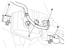
Disconnect the canister close valve connector (A).
|
| 4. |
Disconnect the ventilation hose (B) from the fuel tank air filter
and canister close valve.
|
| 5. |
Remove the fuel tank air filter assembly after removing bolts
(C).
|
| 6. |
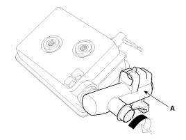
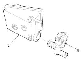
Release the lever (A), and then separate the canister close valve
(B) from the fuel tank air filter (C) after rotating it in the direction
of the arrow in the figure.
|
Installation
|
| 1. |
Installation is reverse of removal.
|
 Canister Close Valve (CCV). Schematic Diagrams
Circuit Diagram
...
See also:
Front Seat. Repair procedures
Replacement
Front Seat Assembly Replacement
1.
Remove the front foot cover.
2.
After loosening the front seat assembly mounting
bolts, ...
Wheel. Repair procedures
Hub Nut Tightening Sequence
Tighten the hub nuts as follows.
Tightening torque :
88.3 ~ 107.9N.m (9.0 ~ 11.0kgf.m, 65.1 ~ 79.6lb-ft)
...
Electrical System
1.
Be sure to disconnect the battery cable from the negative (-)
terminal of the battery.
2.
Never pull on the wires when disconnecting con ...
Categories
- Hyundai Veloster Manuals Home
- Hyundai Veloster 2010-2017 Owner's Manual
- Hyundai Veloster 2010-2017 Service Manual
© 2011-2026 Copyright www.hvmanual.com


