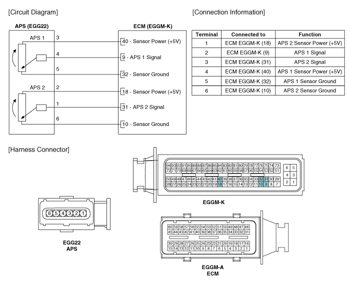
 Hyundai Veloster: Accelerator Position Sensor (APS). Schematic Diagrams
Hyundai Veloster 2011-2017 Service Manual / Fuel System / Engine Control System / Accelerator Position Sensor (APS). Schematic Diagrams
Hyundai Veloster 2011-2017 Service Manual / Fuel System / Engine Control System / Accelerator Position Sensor (APS). Schematic Diagrams
Circuit Diagram

 Accelerator Position Sensor (APS). Specifications
Specification
Accelerator
Position
Output Voltage (V)
APS1
APS2
C.T
0.7 ~ 0.8
0.29 ~ 0.46
...
 Accelerator Position Sensor (APS). Repair procedures
Inspection
1.
Connect the GDS on the Data Link Connector (DLC).
2.
Turn the ignition switch ON.
3.
Measure the ...
See also:
Schematic Diagrams
Circuit Diagram (1)
Circuit Diagram (2)
SRSCM Connector terminal
Pin
Function (Connector A)
Pin
Function (Connector B)
...
SRS Control Module (SRSCM). Description and Operation
Description
The primary purpose of the SRSCM (Supplemental Restraints System Control
Module) is to discriminate between an event that warrants restraint system deployment
and an event that d ...
Opening the tailgate
The tailgate is locked or unlocked when all doors are locked or unlocked
with the key, transmitter, smart key or central door lock/unlock switch.
When all doors are lock if the tailgate unlo ...
Categories
- Hyundai Veloster Manuals Home
- Hyundai Veloster 2010-2017 Owner's Manual
- Hyundai Veloster 2010-2017 Service Manual
В© 2011-2026 Copyright www.hvmanual.com
