 Hyundai Veloster: Schematic Diagrams
Hyundai Veloster 2011-2017 Service Manual / Body Electrical System / Button Engine Start System / Schematic Diagrams
Hyundai Veloster: Schematic Diagrams
Hyundai Veloster 2011-2017 Service Manual / Body Electrical System / Button Engine Start System / Schematic Diagrams
Hyundai Veloster 2011-2017 Service Manual / Body Electrical System / Button Engine Start System / Schematic Diagrams
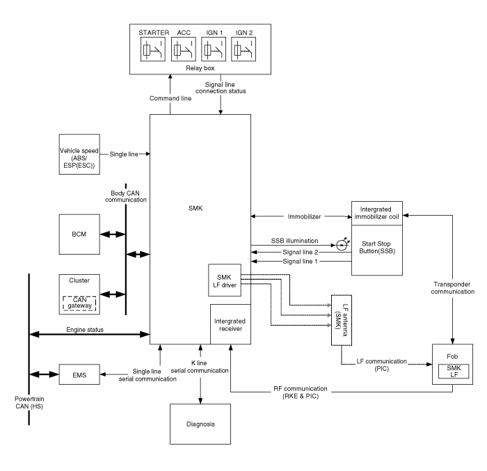
Circuit Diagram (1)
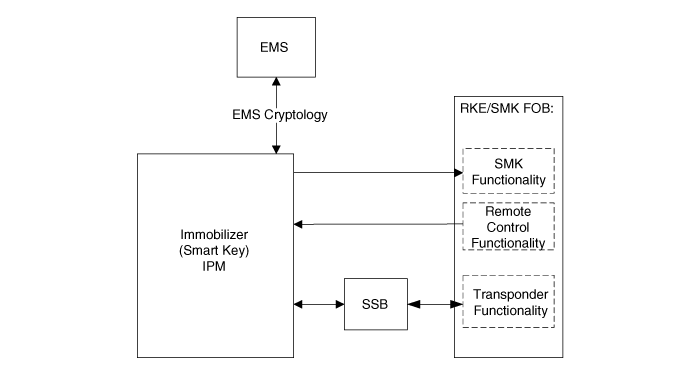
Circuit Diagram (2)
 Components and Components Location
Component Location
1. Start Stop Button(SSB)
2. FOB key
3. Smart key unit
4. Interior antenna 1
5. Interior antenna 2
6. Tailgate antenna
7. Door handle & ...
 Description and Operation
Description
System Overview
The System offers the following features:
-
Human machine interface through a 1-stage button, for terminal
switching and engine start.
...
See also:
SRS Control Module (SRSCM). Components and Components Location
Components
...
Economical operation
Your vehicle's fuel economy depends mainly on your style of driving, where you
drive and when you drive.
Each of these factors affects how many miles (kilometers) you can get from a
gallon (l ...
Light bulbs
WARNING - Working on the lights
Prior to working on the light, firmly apply the parking brake, ensure that
the ignition switch is turned to the LOCK position and turn off the lights to avoid
sudd ...
Categories
- Hyundai Veloster Manuals Home
- Hyundai Veloster 2010-2017 Owner's Manual
- Hyundai Veloster 2010-2017 Service Manual

© 2011-2026 Copyright www.hvmanual.com