 Hyundai Veloster: Rear Glass Defogger Switch. Repair procedures
Hyundai Veloster 2011-2017 Service Manual / Body Electrical System / Rear Glass Defogger / Rear Glass Defogger Switch. Repair procedures
Inspection
| 1. |
The rear glass defogger switch inputs can be checked using the
GDS.
|
| 2. |
To check the input value of rear glass defogger switch, select
option "Body Control Module".
|
| 3. |
To consult the present input/output value of BCM, "Current DATA".
It provides information of BCM input/output conditions of smart junction
box.
|
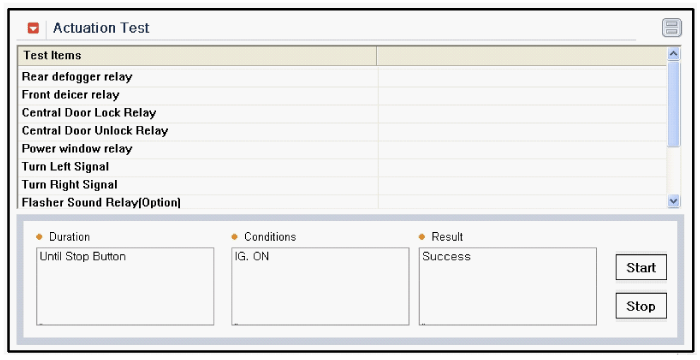
| 4. |
To check the input value of rear glass defogger switch in force
mode, select option "Actuation Test of smart junction box".
|
Removal
| 1. |
Disconnect the negative(-) battery terminal.
|
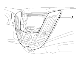
| 2. |
Remove the center fascia panel assembly (A).
(Refer to the Body group - "Crash pad")
|
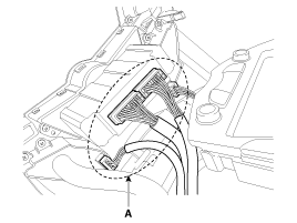
| 3. |
Remove the center fascia panel connector (A).
|
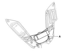
| 4. |
Remove the heater and air corditioner controller (A), after loosening
the screw (4EA).
|
Installation
| 1. |
Install the heater and air conditioner controller to the center
fascia panel.
|
| 2. |
Install the center fascia panel assembly.
|
 Rear Glass Defogger Printed Heater. Repair procedures
Inspection
Wrap tin foil around the end of the voltmeter test lead to prevent
damaging the heater line. Apply finger pressure ...
See also:
Parking Brake Assembly. Components and Components Location
Components
1. Parking brake lever
2. Parking brake cable
3. Equalizer assembly
...
Variable Intake Solenoid (VIS) Valve. Description and Operation
Description
Variable Intake manifold Solenoid (VIS) valve is installed on the intake
manifold. The VIS valve controls the vacuum modulator which activates a valve
in the intake manifold. The ...
IPM (Intelligent integrated Platform Module). Description and Operation
Description
IPM Overview
The Body Control Module (IPM-Intelligent integrated Platform Module) supplies
vehicle occupants with visual and audible information and it controls various
vehic ...
Categories
- Hyundai Veloster Manuals Home
- Hyundai Veloster 2010-2017 Owner's Manual
- Hyundai Veloster 2010-2017 Service Manual


