 Hyundai Veloster: Front Stabilizer Bar. Repair procedures
Hyundai Veloster 2011-2017 Service Manual / Suspension System / Front Suspension System / Front Stabilizer Bar. Repair procedures
Hyundai Veloster: Front Stabilizer Bar. Repair procedures
Hyundai Veloster 2011-2017 Service Manual / Suspension System / Front Suspension System / Front Stabilizer Bar. Repair procedures
Replacement
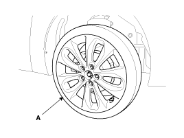
| 1. |
Remove the front wheel & tire.
|
| 2. |
Disconnect the stabilizer link with the front strut assembly after
loosening the nut.
|
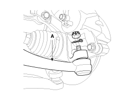
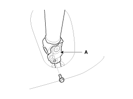
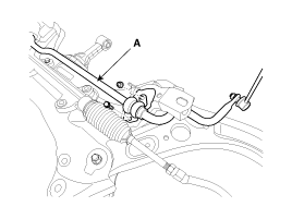
| 3. |
Loosen the nut and then remove the tie-rod end (A) with the front
axle.
|
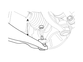
| 4. |
Loosen the nut and then remove the lower arm (A).
|
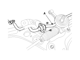
| 5. |
Loosen the bolt (A) and then disconnect the universal joint assembly
from the pinion of the steering gear box.
|
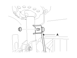
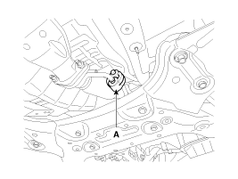
| 6. |
Remove the rubber hanger (A).
|
| 7. |
Loosen the roll rod (A) mounting bolts and nuts.
|
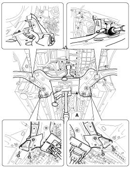
| 8. |
Loosen the bolts & nuts and then remove the front sub frame (A).
|
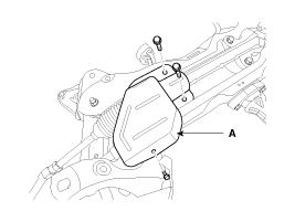
| 9. |
Remove the protecter (A).
[LHD]
[RHD]
|
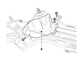
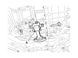
| 10. |
Remove the stabilizer (A) from the front sub frame by loosening
the mounting bolts & nuts.
|
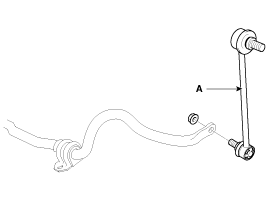
| 11. |
Disconnect the stabilizer link (A) with the stabilizer bar by
loosening the nut.
|
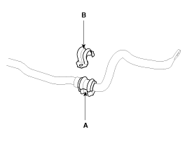
| 12. |
Remove the bushing (A) and the clamp (B) from the stabilizer bar.
|
| 13. |
Installation is the reverse of removal.
|
| 14. |
Check the wheel alignment.
(Refer to SS group - "Tires/Wheels")
|
Inspection
| 1. |
Check the bushing for wear and deterioration.
|
| 2. |
Check the front stabilizer bar for deformation.
|
| 3. |
Check the front stabilizer link ball joint for damage.
|
 Front Lower Arm. Repair procedures
Replacement
1.
Remove the front wheel & tire.
Tightening torque :
88.3 ~ 107.9N.m(9.0 ~ 11.0kgf.m, 65.1 ~ 79.6lb-ft)
...
 Sub Frame. Repair procedures
Replacement
1.
Remove the front wheel & tire.
Tightening torque :
88.3 ~ 107.9N.m(9.0 ~ 11.0kgf.m, 65.1 ~ 79.6lb-ft)
...
See also:
Start/Stop Button. Repair procedures
Removal
1.
Disconnect the negative(-) battery terminal.
2.
Remove the center fascia panel assembly (A).
3.
...
Electric power steering (EPS)
The power steering uses a motor to assist you in steering the vehicle. If the
engine is off or if the power steering system becomes inoperative, the vehicle may
still be steered, but it will requi ...
Front Impact Sensor (FIS). Repair procedures
Removal
•
Removal of the airbag must be performed according to the
precautions/ procedures d ...
Categories
- Hyundai Veloster Manuals Home
- Hyundai Veloster 2010-2017 Owner's Manual
- Hyundai Veloster 2010-2017 Service Manual
