 Hyundai Veloster: Seat Belt Pretensioner (BPT). Repair procedures
Hyundai Veloster 2011-2017 Service Manual / Restraint (Depowered) / Seat Belt Pretensioner / Seat Belt Pretensioner (BPT). Repair procedures
Hyundai Veloster 2011-2017 Service Manual / Restraint (Depowered) / Seat Belt Pretensioner / Seat Belt Pretensioner (BPT). Repair procedures
Removal
| 1. |
Disconnect the battery negative cable, and wait for at least three
minutes before beginning work.
|
| 2. |
Remove the lower anchor bolt.
|
| 3. |
Remove the following parts.
(Refer to the Body group - "Interior trim")
|
| 4. |
Remove the upper anchor bolt.
|
| 5. |
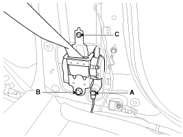
Disconnect the seat belt pretensioner connector (A).
|
| 6. |
Loosen the seat belt pretensioner mounting bolts (B,C) and remove
the seat belt pretensioner.
|
Installation
| 1. |
Remove the ignition key from the vehicle.
|
| 2. |
Disconnect the battery negative cable and wait for at least three
minutes.
|
| 3. |
Install the seat belt pretensioner with a bolts (B, C).
|
| 4. |
Connect the seat belt pretensioner (BPT) connector (A).
|
| 5. |
Install the upper anchor bolts.
|
| 6. |
Install the following parts.
(Refer to the Body group - "Interior trim")
|
| 7. |
Install the lower anchor bolts.
|
| 8. |
Reconnect the battery negative cable.
|
| 9. |
After installing the seat belt pretensioner, confirm proper system
operation:
|

