
 Hyundai Veloster: Repair procedures
Hyundai Veloster 2011-2017 Service Manual / Engine Electrical System / Charging System / Battery / Repair procedures
Hyundai Veloster: Repair procedures
Hyundai Veloster 2011-2017 Service Manual / Engine Electrical System / Charging System / Battery / Repair procedures
Removal and Installation
| 1. |
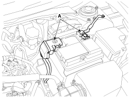
Remove the battery.
|
| 2. |
Remove the air duct and air cleaner assembly. (Refer to EM group).
|
| 3. |
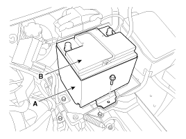
Remove the battery insulation pad (A).
|
| 4. |
Remove the battery (B) after removing the mounting bracket.
|
| 5. |
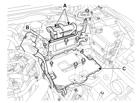
Remove the ECM (B) and the battery tray (C) after disconnecting
the ECM connector (A).
|
| 6. |
Installation is the reverse order of removal.
|

Inspection
Battery Diagnostic Flow
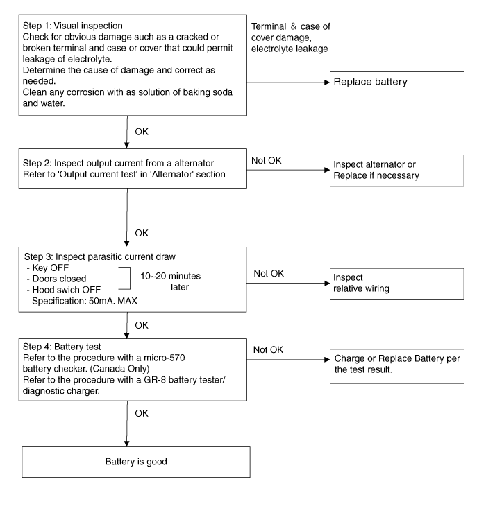
Vehicle parasitic current inspection
| 1. |
Turn all the electric devices OFF, and then turn the ignition
switch OFF.
|
| 2. |
Close all doors except the engine hood, and then lock all doors.
|
| 3. |
Wait a few minutes until the vehicle’s electrical systems go to
sleep mode.
|

| 4. |
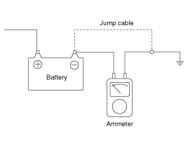
Connect an ammeter in series between the battery (-) terminal
and the ground cable, and then disconnect the clamp from the battery
(-) terminal slowly.
|
| 5. |
Read the current value of the ammeter.
|
Cleaning
| 1. |
Make sure the ignition switch and all accessories are in the OFF
position.
|
| 2. |
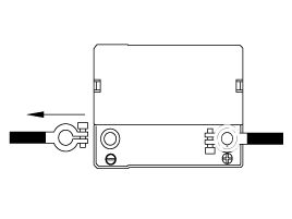
Disconnect the battery cables (negative first).
|
| 3. |
Remove the battery from the vehicle.
|
| 4. |
Inspect the battery tray for damage caused by the loss of electrolyte.
If acid damage is present, it will be necessary to clean the area with
a solution of clean warm water and baking soda. Scrub the area with
a stiff brush and wipe off with a cloth moistened with baking soda and
water.
|
| 5. |
Clean the top of the battery with the same solution as described
above.
|
| 6. |
Inspect the battery case and cover for cracks. If cracks are present,
the battery must be replaced.
|
| 7. |
Clean the battery posts with a suitable battery post tool.
|
| 8. |
Clean the inside surface of the terminal clamps with a suitable
battery cleaning tool. Replace damaged or frayed cables and broken terminal
clamps.
|
| 9. |
Install the battery in the vehicle.
|
| 10. |
Connect the cable terminals to the battery post, making sure tops
of the terminals are flush with the tops of the posts.
|
| 11. |
Tighten the terminal nuts securely.
|
| 12. |
Coat all connections with light mineral grease after tightening.
|
 Components and Components Location
Components
1. Battery insulation pad
2. Battery
3. Battery tray
4. Battery mounting bracket
5. ECM & bracket assembly
...
 Battery Sensor
Description and Operation
Description
Vehicles have many control units that use more electricity. These units
control their own system based on information from diverse sensors. It is importan ...
See also:
IPM (Intelligent integrated Platform Module). Components and Components Location
Components
※ Internal Buzzer : Rear parking assist system buzzer
Signal Characteristics
Symbol
Name
L_
Logic input
...
Changing tires
1. Park on a level surface and apply the parking brake firmly. 2. Shift the
shift lever into R (Reverse) with manual transaxle or P (Park) with automatic transaxle.
3. Activate the hazard warnin ...
Smart key. Repair procedures
Smart Key
Smart Key Code Saving
1.
Connect the DLC cable of GDS to the data link connector in driver
side crash pad lower panel, turn the power on GDS.
...
Categories
- Hyundai Veloster Manuals Home
- Hyundai Veloster 2010-2017 Owner's Manual
- Hyundai Veloster 2010-2017 Service Manual
