 Hyundai Veloster: Power Seat Control Switch. Repair procedures
Hyundai Veloster 2011-2017 Service Manual / Body Electrical System / Seat Electrical / Power Seat Control Switch. Repair procedures
Hyundai Veloster 2011-2017 Service Manual / Body Electrical System / Seat Electrical / Power Seat Control Switch. Repair procedures
Inspection
| 1. |
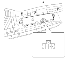
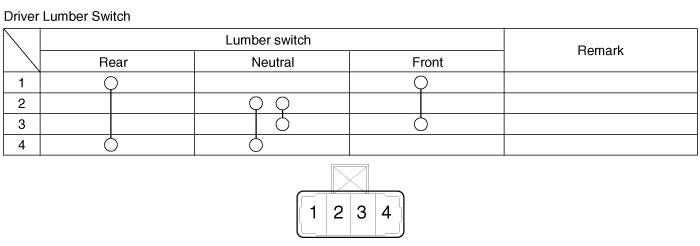
With the lumbar support switch (A) in each position, make sure
that continuity exists between the terminals below. If continuity is
not as specified, replace the lumbar support switch.
|
Removal
| 1. |
Disconnect the negative (-) battery terminal.
|
| 2. |
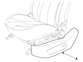
Remove the seat side cover (A).
(Refer to the BD group - "Front seat")
|
| 3. |
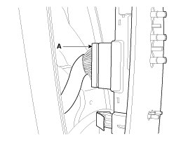
Remove the power seat control switch connector.
|
| 4. |
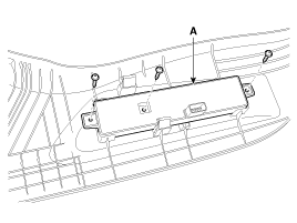
Remove the power seat control switch(A) after loosening the mounting
screw.
|
Installation
| 1. |
Connect the connector and install the power seat control switch.
|
| 2. |
Install the seat cover.
|
 Power Seat Motor. Repair procedures
Inspection
Power seat motor
1.
Remove the seat and Lumbar support motor (A) connectors.
2.
With the battery connected dire ...
 Seat Heater Switch. Schematic Diagrams
Circuit Diagram
...
See also:
Front seat adjustment
Forward and backward
Type A
To move the seat forward or backward:
1. Pull the seat slide adjustment lever up and hold it. 2. Slide the seat to
the position you desire. 3. Release the lever and ...
Gear Actuator > Repair procedures
Removal
1.
Remove the following parts first:
A.
Air cleaner assembly and air duct
(Refer to the Intake and Exhaust System of EM Gro ...
Cruise control system
The cruise control system allows you to program the vehicle to maintain a constant
speed without resting your foot on the accelerator pedal.
This system is designed to function above approximately ...
Categories
- Hyundai Veloster Manuals Home
- Hyundai Veloster 2010-2017 Owner's Manual
- Hyundai Veloster 2010-2017 Service Manual
В© 2011-2026 Copyright www.hvmanual.com

