 Hyundai Veloster: Parking Brake Assembly. Repair procedures
Hyundai Veloster 2011-2017 Service Manual / Brake System / Parking Brake System / Parking Brake Assembly. Repair procedures
Hyundai Veloster: Parking Brake Assembly. Repair procedures
Hyundai Veloster 2011-2017 Service Manual / Brake System / Parking Brake System / Parking Brake Assembly. Repair procedures
Hyundai Veloster 2011-2017 Service Manual / Brake System / Parking Brake System / Parking Brake Assembly. Repair procedures
Removal
The parking brake cables must not be bent or distorted. This will
lead to stiff operation and premature failure.
|
| 1. |
Remove the floor console.
(Refer to Body group - "Floor console")
|
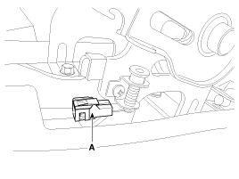
| 2. |
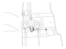
Disconnect the connector (A) of parking brake switch.
|
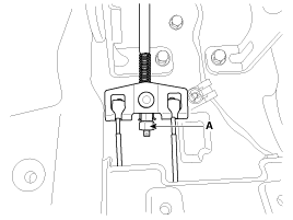
| 3. |
Loosen the adjusting nut (A) and the parking brake cables.
|
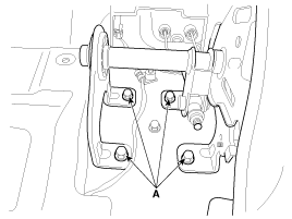
| 4. |
Remove the parking brake lever assembly after removing the bolts
(A).
|
| 5. |
Raise the vehicle, and make sure it is securely supported.
|
| 6. |
Remove the rear tire and wheel.
|
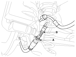
| 7. |
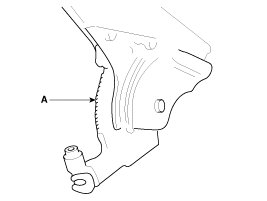
Remove the parking brake cable (B), after removing the clip (A).
|
| 8. |
Loosen the parking brake cable bracket bolts and remove the parking
brake cable.
|
Installation
| 1. |
Install the parking brake cable.
|
| 2. |
Install the parking brake cable (B), and then install the clip
(A).
|
| 3. |
Install the rear tire and wheel.
|
| 4. |
Install the parking brake lever assembly.
|
| 5. |
Install the parking brake cable.
|
| 6. |
Apply a coating of the specified grease to each sliding parts
(A) of the ratchet plate or the ratchet pawl.
|
| 7. |
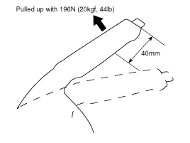
Install the parking brake cable adjuster, then adjust the parking
brake lever stroke by turning adjusting nut (A).
|
| 8. |
Release the parking brake lever fully, and check that parking
brakes do not drag when the rear wheels are turned. Readjust if necessary.
|
| 9. |
Make sure that the parking brakes are fully applied when the parking
brake lever is pulled up fully.
|
| 10. |
Reconnect the connector (A) of parking brake switch.
|
| 11. |
Install the floor console.
(Refer to Body group - "Floor console")
|
Adjustment
| Parking Brake Lever Stroke Adjustment |
| 1. |
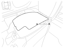
Remove the floor console tray mat (A).
|
| 2. |
Install the parking brake cable adjuster, then adjust the parking
brake lever stroke by turning adjusting nut (A).
|
| 3. |
Release the parking brake lever fully, and check that parking
brakes do not drag when the rear wheels are turned. Readjust if necessary.
|
| 4. |
Make sure that the parking brakes are fully applied when the parking
brake lever is pulled up fully.
|
| 5. |
Install thd floor console tray mat (A).
|
 Parking Brake Assembly. Components and Components Location
Components
1. Parking brake lever
2. Parking brake cable
3. Equalizer assembly
...

See also:
ETC (Electronic Throttle Control) System. Troubleshooting
Fail-Safe Mode
Item
Fail-Safe
ETC Motor
Throttle valve stuck at 7°
TPS
TPS 1 fault
ECM looks at TPS2
...
Loss of the smart key
A maximum of 2 smart keys can be registered to a single vehicle.
If you happen to lose your smart key, you will not be able to start the engine.
You should immediately take the vehicle and remainin ...
Master Cylinder. Components and Components Location
Components
1. Reservoir cap
2. Reservoir
3. Grommet
4. Master cylinder assembly
...
Categories
- Hyundai Veloster Manuals Home
- Hyundai Veloster 2010-2017 Owner's Manual
- Hyundai Veloster 2010-2017 Service Manual

© 2011-2026 Copyright www.hvmanual.com