 Hyundai Veloster: Manifold Absolute Pressure Sensor (MAPS). Repair procedures
Hyundai Veloster 2011-2017 Service Manual / Fuel System / Engine Control System / Manifold Absolute Pressure Sensor (MAPS). Repair procedures
Hyundai Veloster 2011-2017 Service Manual / Fuel System / Engine Control System / Manifold Absolute Pressure Sensor (MAPS). Repair procedures
Inspection
| 1. |
Connect the GDS on the Data Link Connector (DLC).
|
| 2. |
Measure the output voltage of the MAPS at idle and IG ON.
|
Removal
| 1. |
Turn the ignition switch OFF and disconnect the battery negative
(-) cable.
|
| 2. |
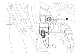
Disconnect the manifold absolute pressure sensor connector (A).
|
| 3. |
Remove the installation bolt (B), and then remove the sensor from
the surge tank.
|
Installation
|
|
| 1. |
Installation is reverse of removal.
|
 Manifold Absolute Pressure Sensor (MAPS). Schematic Diagrams
Circuit Diagram
...
 Intake Air Temperature Sensor (IATS). Description and Operation
Description
Intake Air Temperature Sensor (IATS) is included inside Manifold Absolute
Pressure Sensor and detects the intake air temperature.
To calculate precise air quantity, correction o ...
See also:
Console. Repair procedures
Replacement
Floor Console Replacement
[M/T]
•
A plastic trim tool is recommended, ...
Parking brake
Applying the parking brake
To engage the parking brake, first apply the foot brake and then pull up the
parking brake lever as far as possible without pressing the release button.
In addition it ...
Special Service Tools
Special Service Tools
Tool
(Number and name)
Illustration
Use
09200-38001,3N000 (Beam)
09200-4X000 (Adapter)
09200-2S100, 2S200 (Support ...
Categories
- Hyundai Veloster Manuals Home
- Hyundai Veloster 2010-2017 Owner's Manual
- Hyundai Veloster 2010-2017 Service Manual
© 2011-2026 Copyright www.hvmanual.com

