 Hyundai Veloster: ETC (Electronic Throttle Control) System. Repair procedures
Hyundai Veloster 2011-2017 Service Manual / Fuel System / Engine Control System / ETC (Electronic Throttle Control) System. Repair procedures
Hyundai Veloster 2011-2017 Service Manual / Fuel System / Engine Control System / ETC (Electronic Throttle Control) System. Repair procedures
Inspection
Throttle Position Sensor (TPS)
| 1. |
Connect the GDS on the Data Link Connector (DLC).
|
| 2. |
Start the engine and measure the output voltage of TPS 1 and 2
at C.T. and W.O.T.
|
|||||||||||
ETC Motor
| 1. |
Turn the ignition switch OFF.
|
| 2. |
Disconnect the ETC module connector.
|
| 3. |
Measure resistance between the ETC module terminals 1 and 2.
|
| 4. |
Check that the resistance is within the specification.
|
Removal
| 1. |
Turn the ignition switch OFF and disconnect the battery negative
(-) cable.
|
| 2. |
Remove the resonator and the air intake hose (Refer to “Intake
And Exhaust System” in EM group).
|
| 3. |
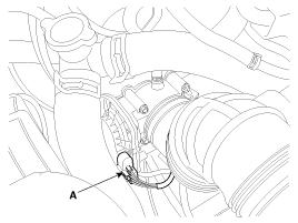
Disconnect the ETC module connector (A).
|
| 4. |
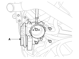
Remove the installation bolts, and then remove the ETC module
(A) from the engine.
|
Installation
|
| 1. |
Installation is reverse of removal.
|
Adjustment
| ETC module learning procedure |
When installing new ETC module or re-installing it, ETC module learning
procedure must be performed.
| 1. |
Hold the ignition key or the start button at th IG ON position
during 5 seconds.
|
| 2. |
Turn ignition swich OFF and then start the engine.
|
DTC codes (P0638, P2110) might be displayed if ETC module learning
procedure does not performed after replacing ETC module.
|
 ETC (Electronic Throttle Control) System. Schematic Diagrams
Circuit Diagram
...
 Manifold Absolute Pressure Sensor (MAPS). Description and Operation
Description
Manifold Absolute Pressure Sensor (MAPS) is a speed-density type sensor
and is installed on the surge tank. It senses absolute pressure of the surge
tank and transfers the analog ...
See also:
Components and Components Location
Component Location
1. Driver power window main switch
2. Passenger power window switch
3. Front window motor
4. Rear window motor
5. Rear window switch
...
Troubleshooting
Troubleshooting
Trouble Symptom
Probable cause
Remedy
Vehicle pulls to one side
Scoring of driveshaft ball joint
Replace
...
Front Repair procedures
Replacement
•
Put on gloves to protect your hands.
•
...
Categories
- Hyundai Veloster Manuals Home
- Hyundai Veloster 2010-2017 Owner's Manual
- Hyundai Veloster 2010-2017 Service Manual
© 2011-2026 Copyright www.hvmanual.com


