 Hyundai Veloster: Passive Occupant Detection System (PODS-F). Repair procedures
Hyundai Veloster 2011-2017 Service Manual / Restraint (Advanced) / SRSCM / Passive Occupant Detection System (PODS-F). Repair procedures
Removal
| 1. |
Disconnect the battery negative cable, and wait for at least three
minutes before beginning work.
|
| 2. |
Remove the front passenger seat assembly.
(Refer to the Body group - "Seat")
|
| 3. |
Disconnect the PODS-F ECU connector.
|
| 4. |
Remove the seat cushion cover assembly.
(Refer to the Body group - "Seat")
|
| 5. |
Remove the seat track assembly.
(Refer to the Body group - "Seat")
|
| 1. |
Disconnect the battery negative cable, and wait for at least three
minutes before beginning work.
|
| 2. |
Remove the front passenger seat assembly.
(Refer to the Body group - "Seat")
|
| 3. |
Disconnect the PODS-F mat connector.
|
| 4. |
Remove the seat cushion assembly.
(Refer to the Body group - "Seat")
|
Installation
| 1. |
Install the PODS-F ECU equipped seat track assembly.
(Refer to the Body group - "Seat")
|
| 2. |
Install the seat cushion cover assembly.
(Refer to the Body group - "Seat")
|
| 3. |
Connect the PODS-F ECU connector.
|
| 4. |
Install the front passenger seat assembly.
(Refer to the Body group - "Seat")
|
| 5. |
Reconnect the battery negative cable.
|
| 6. |
After installing the PODS-F, confirm proper system operation :
|
| 1. |
Install the PODS-F Mat equipped seat cushion assembly.
(Refer to the Body group - "Seat")
|
| 2. |
Install the front passenger seat assembly.
(Refer to the Body group - "Seat")
|
| 3. |
Connect the PODS-F mat connector.
|
| 4. |
Reconnect the battery negative cable.
|
| 5. |
After installing the PODS-F, confirm proper system operation :
|
PODS-F Zeroing procedure
| 1. |
Ignition “OFF”, connect GDS.
|
| 2. |
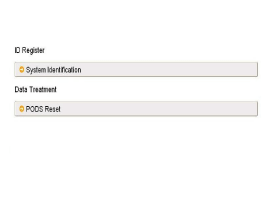
Ignition “ON” & Engine “OFF”, select Airbag system and “PODS-F
Reset” mode.
|
| 3. |
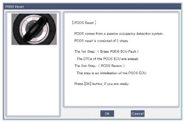
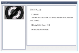
The GDS will show the two PODS-F Zeroing function steps.
|
| 4. |
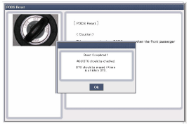
The PODS-F initialization procedure will be performed.
|
 Schematic Diagrams
Circuit Diagram (1)
Circuit Diagram (2)
Circuit Diagram (3)
SRSCM Connector terminal
Pin
Function (Connector A)
Pin
Function (Co ...
See also:
Closing the hood
1. Before closing the hood, check the following:
• All filler caps in engine compartment must be correctly installed. • Gloves,
rags or any other combustible material must be removed from the e ...
Main components of occupant classification system
A detection device located within the front passenger seat frame.
Electronic system to determine whether the front passenger air bag system
should be activated or deactivated.
A warning ligh ...
Hill-start assist control (HAC)
A vehicle has the tendency to slip back on a steep hill when the driver begins
to accelerate after a stop. The Hill-start Assist Control (HAC) prevents the vehicle
from slipping back by operating ...
Categories
- Hyundai Veloster Manuals Home
- Hyundai Veloster 2010-2017 Owner's Manual
- Hyundai Veloster 2010-2017 Service Manual


