 Hyundai Veloster: Manual Transaxle. Repair procedures
Hyundai Veloster 2011-2017 Service Manual / Manual Transaxle System (M6CF1) / Manual Transaxle System / Manual Transaxle. Repair procedures
Hyundai Veloster: Manual Transaxle. Repair procedures
Hyundai Veloster 2011-2017 Service Manual / Manual Transaxle System (M6CF1) / Manual Transaxle System / Manual Transaxle. Repair procedures
Hyundai Veloster 2011-2017 Service Manual / Manual Transaxle System (M6CF1) / Manual Transaxle System / Manual Transaxle. Repair procedures
Removal
| 1. |
Remove the following items;
|
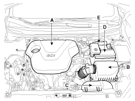
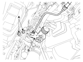
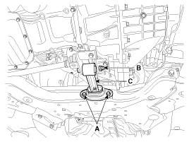
| 2. |
Disconnect the vehicle speed sensor connector (A).
|
| 3. |
Remove the back up lamp switch connector (B).
|
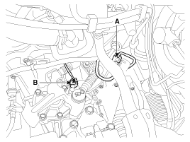
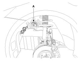
| 4. |
Remove the ground cable from transaxle (A).
|
| 5. |
Disconnect the shift cable bracket bolts (B-3ea)
after removing the washer and pin (A).
|
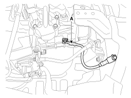
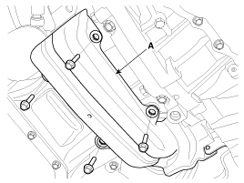
| 6. |
Remove the tube bracket bolt (A).
|
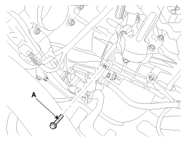
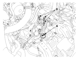
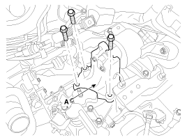
| 7. |
Remove the transaxle upper mounting bolt (B-2ea)
and the start motor mounting bolt (A-2ea).
|
| 8. |
Remove the cowl top cover.
(Refer to "Interior(cowl top cover)" in BD group.)
|
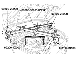
| 9. |
Using the engine support fixture (Support SST No.:
09200-2S100/2S200, Adapter SST No.: 09200-4X000, Beam SST No.: 09200-38001/3N000),
hold the engine and transaxle assembly safely.
|
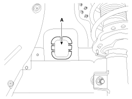
| 10. |
Remove the mounting cover (A).
|
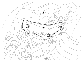
| 11. |
Remove the transaxle support mounting bracket bolts
(A-2ea).
|
| 12. |
Remove the transaxle support mounting bracket (A).
|
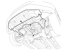
| 13. |
Remove the under cover (A).
|
| 14. |
Remove the drive shaft assembly.
(Refer to "Drive shaft assembly" in DS group.)
|
| 15. |
Remove the clutch release cylinder assembly (B) after
removing the nuts (A-2ea).
|
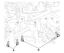
| 16. |
Remove the roll rod support bracket (C) after removing
bolt (A,B).
|
| 17. |
Remove the drive shaft cover (A).
|
| 18. |
Remove the brackets (A).
|
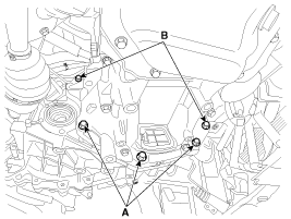
| 19. |
Remove the lower mounting bolts (A-3ea, B-2ea) of
lower part of the transaxle, and remove the transaxle assembly by supporting
it with a jack.
|
Installation
| 1. |
Installation is the reverse of removal.
|
 Manual Transaxle. Components and Components Location
Components
1. Transaxle support bracket
2. Control shaft complete
3. Back up lamp switch
4. Speedmeter
...

See also:
Parking Brake Assembly. Components and Components Location
Components
1. Parking brake lever
2. Parking brake cable
3. Equalizer assembly
...
Rear Washer Motor. Repair procedures
Inspection
1.
With the washer motor connected to the reservoir tank, fill the
reservoir tank with water.
...
Components and Components Location
Components
1. TPMS Receiver
2. TPMS Sensor (FL)
3. TPMS Sensor (RL)
4. TPMS Sensor (RR)
5. TPMS Sensor (FR)
...
Categories
- Hyundai Veloster Manuals Home
- Hyundai Veloster 2010-2017 Owner's Manual
- Hyundai Veloster 2010-2017 Service Manual

© 2011-2026 Copyright www.hvmanual.com