 Hyundai Veloster: Fuel Pump. Repair procedures
Hyundai Veloster 2011-2017 Service Manual / Fuel System / Fuel Delivery System / Fuel Pump. Repair procedures
Hyundai Veloster 2011-2017 Service Manual / Fuel System / Fuel Delivery System / Fuel Pump. Repair procedures
Removal
| 1. |
Release the residual pressure in fuel line (Refer to ŌĆ£Release
Residual Pressure in Fuel LineŌĆØ in this group).
|
| 2. |
Remove the rear seat [LH] (Refer to ŌĆ£SeatŌĆØ in BD group).
|
| 3. |
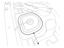
Remove the fuel pump service cover (A).
|
| 4. |
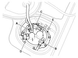
Disconnect the fuel pump connector (A).
|
| 5. |
Disconnect the fuel feed tube quick connector (B).
|
| 6. |
Disconnect the fuel tank pressure sensor connector (C).
|
| 7. |
Disconnect the vapor tube quick-connector (D).
|
| 8. |
Remove the plate cover (E) after removing the installation bolts,
and then remove the fuel pump from the fuel tank.
|
Installation
| 1. |
Installation is reverse of removal.
|
Inspection
[Fuel pump]
| 1. |
Turn ignition switch OFF and disconnect the negative (-)battery
cable.
|
| 2. |
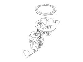
Remove the fuel pump assembly.
|
| 3. |
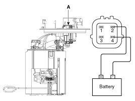
Check motor operation by fuel pump connector (A) connecting power(No.2)
and ground(No.4)
|
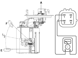
[Fuel sender]
| 1. |
Using an ohmmeter, measure the resistance between terminals 1
and 3 of sender connector (A) at each float level.
|
| 2. |
Also check that the resistance changes smoothly when the float
is moved from "E" to "F".
|
 Fuel Tank. Repair procedures
Removal
1.
Release the residual pressure in fuel line (Refer to ŌĆ£Release
Residual Pressure in Fuel LineŌĆØ in this group).
2.
Remove the ...
 Fuel Filter. Repair procedures
Replacement
1.
Remove the fuel pump (Refer to ŌĆ£Fuel PumpŌĆØ in this group).
2.
Disconnect the electric pump wiring connector (A) and the fuel ...
See also:
Passenger Airbag (PAB) Module. Description and Operation
Description
The passenger airbag (PAB) is installed inside the crash pad and protects
the front passenger in the event of a frontal crash. The SRSCM determines if
and when to deploy the PAB. ...
MTS Antenna. Components and Components Location
Components
...
Components and Components Location
Component Location
1. DCT (Dual Clutch Transmission)
2. DCT Control Module
3. Shift Lever
4. Data Link Connector (DLC)
...
Categories
- Hyundai Veloster Manuals Home
- Hyundai Veloster 2010-2017 Owner's Manual
- Hyundai Veloster 2010-2017 Service Manual
┬® 2011-2025 Copyright www.hvmanual.com

