
 Hyundai Veloster: Clutch Cover And Disc. Repair procedures
Hyundai Veloster 2011-2017 Service Manual / Clutch System / Clutch System / Clutch Cover And Disc. Repair procedures
Hyundai Veloster: Clutch Cover And Disc. Repair procedures
Hyundai Veloster 2011-2017 Service Manual / Clutch System / Clutch System / Clutch Cover And Disc. Repair procedures
Hyundai Veloster 2011-2017 Service Manual / Clutch System / Clutch System / Clutch Cover And Disc. Repair procedures
Removal
| 1. |
Remove the transaxle assembly.
(Refer to "Manual transaxle system" in MT group)
|
| 2. |
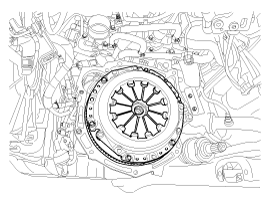
Remove the clutch cover bolts. Be careful not to be bent ortwist
bolts. Loosen bolts in diagonal directions.
|
Inspection
| 1. |
Inspect diaphragm spring wear which is in contact with a concentric
slave cylinder bearing.
|
| 2. |
Check the clutch cover and disc surface for wear or cracks.
|
| 3. |
Check the clutch disc lining for slipping or oil marks.
|
| 4. |
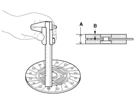
Measure the depth from a clutch lining surface to a rivet. If
the measured value is less than the specification below, replace it.
|
Installation
If reinstalling used cover, the cover should be installed with
its clutch disc as a set.
|

| 1. |
Replace a clutch cover and disc as a set.
|
| 2. |
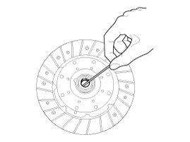
Apply grease on a disc spline part and transmission input shaft
spline part as required.
|
| 3. |
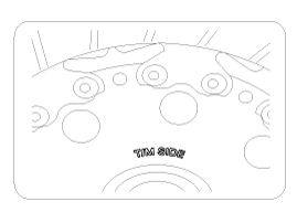
The 'T/M SIDE' marked surface should face the transmission .
|

| 4. |
Install the clutch disc and the cover with SST(A : 09411-1P000).
|
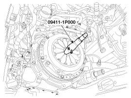
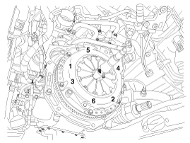
| 5. |
Install the clutch cover bolts. Not to be bent or twisted, Tighten
them in diagonal directions.
|
| 6. |
Install the transaxle assembly.
(Refer to "Manual transaxle system" in MT group)
|
 Clutch Cover And Disc. Components and Components Location
Components
1. Clutch release fork
2. Clutch cover assembly
3. Clutch disk assembly
4. Clutch release bearing
...
 Clutch Master Cylinder. Components and Components Location
Components
1. Reverse hose
2. Master cylinder
3. Ignition lock switch
4. Clutch switch
5. Clutch arm assembly
6. Pedal pad
...
See also:
Specifications
Specification
Description
Specification
Ultrasonic sensor
Rated voltage
DC 12V
Detecting range
11.8~47.2 i ...
Tire replacement
If the tire is worn evenly, a tread wear indicator will appear as a solid band
across the tread. This shows there is less than 1/16 inch (1.6 mm) of tread left
on the tire. Replace the tire when ...
Engine start/stop button position
OFF
• with manual transaxle
To turn off the engine, stop the vehicle then press the engine start/stop button
with the engine start/stop button ON.
• with DCT
To turn off the engine, press th ...
Categories
- Hyundai Veloster Manuals Home
- Hyundai Veloster 2010-2017 Owner's Manual
- Hyundai Veloster 2010-2017 Service Manual

© 2011-2026 Copyright www.hvmanual.com