 Hyundai Veloster: Starter Relay
Hyundai Veloster 2011-2017 Service Manual / Engine Electrical System / Starting System / Starter Relay
Hyundai Veloster: Starter Relay
Hyundai Veloster 2011-2017 Service Manual / Engine Electrical System / Starting System / Starter Relay
Repair procedures
Inspection
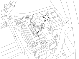
| 1. |
Remove the fuse box cover.
|
| 2. |
Remove the starter relay (A).
|
| 3. |
Using an ohmmeter, check that there is continuity between each
terminal.
|
| 4. |
Apply 12V to terminal 85 and ground to terminal 86.
Check for continuity between terminals 30 and 87.
|
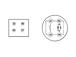
| 5. |
If there is no continuity, replace the starter relay.
|
| 6. |
Install the starter relay.
|
| 7. |
Install the fuse box cover.
|
 Starter
Repair procedures
Removal and Installation
1.
Disconnect the battery negative terminal.
2.
Remove the air duct and air cleaner assembly. (Refe ...

See also:
Description and Operation
OBD-II review
1. Overview
The California Air Resources Board (CARB) began regulation of On Board
Diagnostics (OBD) for vehicles sold in California beginning with the 1988 model
year. T ...
SRS Control Module (SRSCM). Description and Operation
Description
The primary purpose of the SRSCM (Supplemental Restraints System Control
Module) is to discriminate between an event that warrants restraint system deployment
and an event that d ...
DCT Control Modle (TCM) > Repair procedures
Inspection
TCM Inspection Procedure
1.
Inspecting TCM ground circuit: Measure the resistance between
the TCM and chassis ground.
(Check the termina ...
Categories
- Hyundai Veloster Manuals Home
- Hyundai Veloster 2010-2017 Owner's Manual
- Hyundai Veloster 2010-2017 Service Manual
