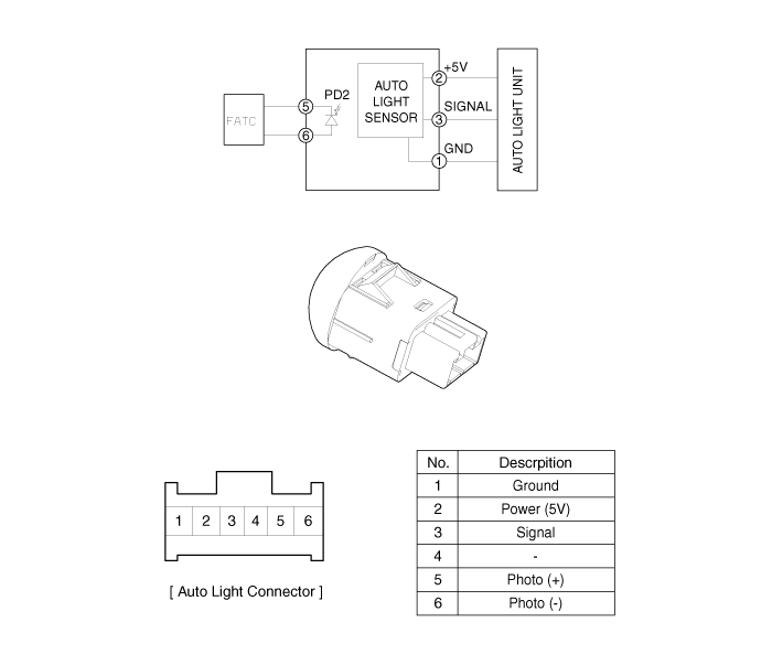
 Hyundai Veloster: Schematic Diagrams
Hyundai Veloster 2011-2017 Service Manual / Body Electrical System / Auto Lighting Control System / Schematic Diagrams
Hyundai Veloster 2011-2017 Service Manual / Body Electrical System / Auto Lighting Control System / Schematic Diagrams
Circuit Diagram

 Components and Components Location
Component Location
1. Auto light sensor
2. Head lamps
3. Lighting switch (Auto)
4. Tail lamps
5. Body control module (BCM)
...
 Auto Light Sensor. Repair procedures
Inspection
In the state of IGN1 ON, when multifunction switch module detects auto
light switch on, tail lamp relay output and head lamp low relay output are controlled
according to auto ligh ...
See also:
Reset items
Items should be reset after the battery has been discharged or the battery has
been disconnected.
Auto up/down window (See section 4)
Sunroof (See section 4)
Trip computer (See section 4)
...
Cup holder
WARNING - Hot liquids
• Do not place uncovered cups of hot liquid in the cup holder while the
vehicle is in motion. If the hot liquid spills, you may burn yourself. Such
a burn to the driv ...
Navigation system
The navigation system ascertains the present position of your vehicle by using
information from satellites and guides you to the place you assign as the destination.
Detailed information for the na ...
Categories
- Hyundai Veloster Manuals Home
- Hyundai Veloster 2010-2017 Owner's Manual
- Hyundai Veloster 2010-2017 Service Manual
© 2011-2026 Copyright www.hvmanual.com
