 Hyundai Veloster: Schematic Diagrams
Hyundai Veloster 2011-2017 Service Manual / Suspension System / Tire Pressure Monitoring System / Schematic Diagrams
Hyundai Veloster: Schematic Diagrams
Hyundai Veloster 2011-2017 Service Manual / Suspension System / Tire Pressure Monitoring System / Schematic Diagrams
Hyundai Veloster 2011-2017 Service Manual / Suspension System / Tire Pressure Monitoring System / Schematic Diagrams
System circuit diagram
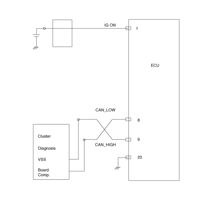
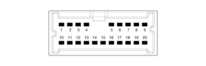
| Connector pin number |
|
Pin No. |
Discription |
Remark |
|
1 |
IG ON |
|
|
2 |
- |
|
|
3 |
- |
|
|
4 |
- |
|
|
5 |
- |
|
|
6 |
- |
|
|
7 |
- |
|
|
8 |
CAN_Low |
|
|
9 |
CAN_High |
|
|
10 |
- |
|
|
11 |
- |
|
|
12 |
- |
|
|
13 |
- |
|
|
14 |
- |
|
|
15 |
- |
|
|
16 |
- |
|
|
17 |
- |
|
|
18 |
- |
|
|
19 |
- |
|
|
20 |
GND |
|
 Components and Components Location
Components
1. TPMS Receiver
2. TPMS Sensor (FL)
3. TPMS Sensor (RL)
4. TPMS Sensor (RR)
5. TPMS Sensor (FR)
...
 Troubleshooting
System self diagnosis
Possible to detect abnormal situations from Sensor data
•
High Temperature – Sensor's temperature is more than 100 °C
•
...
See also:
Antenna. Repair procedures
Inspection
Glass Antenna Test
1.
Wrap aluminum foil (A) around the tip of the tester probe (B)
as shown.
2.
Touch one tester p ...
ETC (Electronic Throttle Control) System. Repair procedures
Inspection
Throttle Position Sensor (TPS)
1.
Connect the GDS on the Data Link Connector (DLC).
2.
Start the engine and measure the output ...
Steering Angle Sensor. Description and Operation
Description
The Steering Angle Sensor (SAS) is installed in MDPS (Motor Driven Power
Steering) and it sends messages to HECU through CAN communication line.
The SAS is used to determine tur ...
Categories
- Hyundai Veloster Manuals Home
- Hyundai Veloster 2010-2017 Owner's Manual
- Hyundai Veloster 2010-2017 Service Manual

© 2011-2025 Copyright www.hvmanual.com