 Hyundai Veloster: Cruise Control Switch
Hyundai Veloster 2011-2017 Service Manual / Engine Electrical System / Cruise Control System / Cruise Control Switch
Repair procedures
Removal and Installation
| 1. |
Disconnect the battery negative terminal.
|
| 2. |
Remove the driver airbag module. (Refer to the RT group - "Airbag
module")
|
| 3. |
Remove the steering wheel. (Refer to the ST group - "Steering
column and shaft")
|
| 4. |
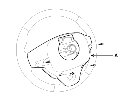
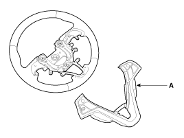
Remove the steering wheel cover (A) after loosening the screws.
|
| 5. |
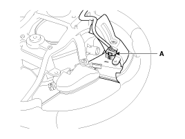
Disconnect the audio switch connector (A).
|
| 6. |
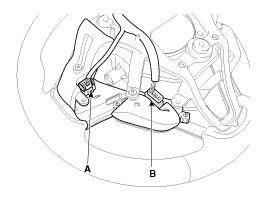
Disconnect the cruise control switch connector (A) and the trip
switch connector (B).
|
| 7. |
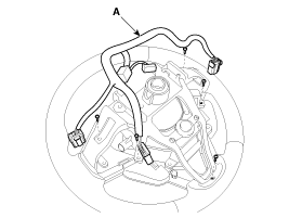
Disconnect the wiring (A) and then loosen the screws.
|
| 8. |
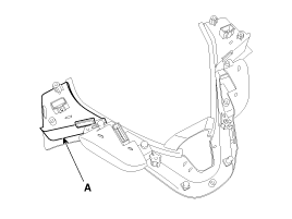
Remove the steering wheel remote control switch assembly (A).
|
| 9. |
Remove the cruise control switch (A).
|
| 10. |
Installation is reverse order of removal.
|
Inspection
Measuring Resistance
| 1. |
Disconnect the cruise control switch connector from the control
switch.
|
| 2. |
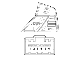
Measure resistance between terminals on the control switch when
each function switch is ON (switch is depressed).
|
| 3. |
If not within specification, replace switch.
|
Measuring Voltage
| 1. |
Connect the cruise control switch connector to the control switch.
|
| 2. |
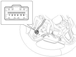
Measure voltage between terminals on the harness side connector
when each function switch is ON (switch is depressed).
|
| 3. |
If not within specification, replace switch.
|
 Cruise Control Switch
Schematic Diagrams
Circuit Diagram
...
See also:
Purge Control Solenoid Valve (PCSV). Repair procedures
Inspection
1.
Turn the ignition switch OFF.
2.
Disconnect the PCSV connector.
3.
Measure resistance between th ...
Air bag - advanced supplemental restraint system
(1) Driver’s front air bag (2) Passenger’s front air bag (3) Side impact
air bag (4) Curtain air bag
WARNING
Even in vehicles with air bags, you and your passengers must always wear the
se ...
Schematic Diagrams
Circuit Diagram (1)
Circuit Diagram (2)
SRSCM Connector terminal
Pin
Function (Connector A)
Pin
Function (Connector B)
...
Categories
- Hyundai Veloster Manuals Home
- Hyundai Veloster 2010-2017 Owner's Manual
- Hyundai Veloster 2010-2017 Service Manual

