 Hyundai Veloster: Repair procedures
Hyundai Veloster 2011-2017 Service Manual / Engine Electrical System / Charging System / Alternator / Repair procedures
Hyundai Veloster: Repair procedures
Hyundai Veloster 2011-2017 Service Manual / Engine Electrical System / Charging System / Alternator / Repair procedures
Hyundai Veloster 2011-2017 Service Manual / Engine Electrical System / Charging System / Alternator / Repair procedures
Removal and installation
| 1. |
Disconnect the battery negative terminal first, then the positive
terminal.
|
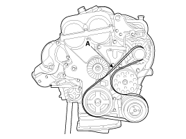
| 2. |
Remove the drive belt.
|
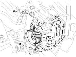
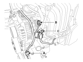
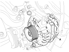
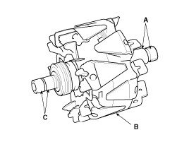
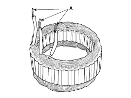
| 3. |
Disconnect the A/C compressor switch connector (A), the alternator
connector (B) and the cable from the alternator "B" terminal (C).
|
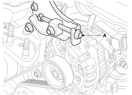
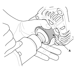
| 4. |
Remove the alternator (A).
|
| 5. |
Installation is the reverse order of removal.
|
| 6. |
Adjust the alternator belt tension after installation.
|
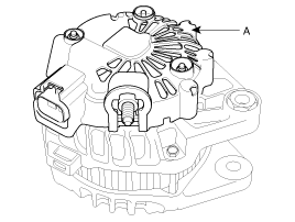
Disassembly
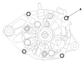
| 1. |
Remove the alternator cover(A).
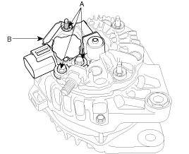
|
| 2. |
Loosen the mounting bolts(A) and disconnect the brush holder assembly(B).
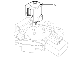
|
| 3. |
Remove the slip ring guide(A).
|
| 4. |
Remove the nut and pulley(A).
|
| 5. |
Loosen the 4 through bolts(A).
|
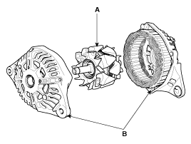
| 6. |
Disconnect the rotor(A) and cover(B).
|
| 7. |
Reassembly is the reverse of disassembly.
|
Inspection
Inspect Rotor
| 1. |
Check that there is continuity between the slip rings (C).
|
| 2. |
Check that there is no continuity between the slip rings and the
rotor (B) or rotor shaft (A).
|
| 3. |
If the rotor fails either continuity check, replace the alternator.
|
Inspect Stator
| 1. |
Check that there is continuity between each pair of leads (A).
|
| 2. |
Check that there is no continuity between each lead and the coil
core.
|
| 3. |
If the coil fails either continuity check, replace the alternator.
|
 Components and Components Location
Components
1. Pulley
2. Front housing
3. Front bearing
4. Stator
5. Rotor
6. Rear bearing
7. Rear housing
8. Regulator assembly
9. Through bolt
...
 Battery
...
See also:
Rear Hub - Carrier. Repair procedures
Replacement
1.
Loosen the wheel nuts slightly.
Raise the vehicle, and make sure it is securely supported.
2.
Remove the rear wheel and ...
Repair procedures
Removal
Back View Camera
1.
Disconnect the negative(-) battery terminal.
2.
Remove the tailgate outside handle assembly.
(Refer to ...
Variable Intake Solenoid (VIS) Valve. Schematic Diagrams
Circuit Diagram
...
Categories
- Hyundai Veloster Manuals Home
- Hyundai Veloster 2010-2017 Owner's Manual
- Hyundai Veloster 2010-2017 Service Manual

© 2011-2024 Copyright www.hvmanual.com