 Hyundai Veloster: Fuel Tank. Repair procedures
Hyundai Veloster 2011-2017 Service Manual / Fuel System / Fuel Delivery System / Fuel Tank. Repair procedures
Hyundai Veloster: Fuel Tank. Repair procedures
Hyundai Veloster 2011-2017 Service Manual / Fuel System / Fuel Delivery System / Fuel Tank. Repair procedures
Hyundai Veloster 2011-2017 Service Manual / Fuel System / Fuel Delivery System / Fuel Tank. Repair procedures
Removal
| 1. |
Release the residual pressure in fuel line (Refer to ŌĆ£Release
Residual Pressure in Fuel LineŌĆØ in this group).
|
| 2. |
Remove the rear seat [LH] (Refer to ŌĆ£SeatŌĆØ in BD group).
|
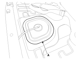
| 3. |
Remove the fuel pump service cover (A).
|
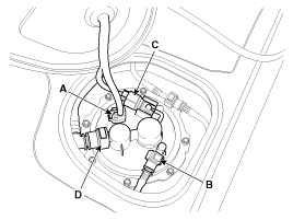
| 4. |
Disconnect the fuel pump connector (A).
|
| 5. |
Disconnect the fuel feed tube quick connector (B).
|
| 6. |
Disconnect the fuel tank pressure sensor connector (C).
|
| 7. |
Disconnect the vapor tube (D).
|
| 8. |
Lift the vehicle and support the fuel tank with a jack.
|
| 9. |
Remove the center muffler assembly (Refer to ŌĆ£Intake And Exhaust
SystemŌĆØ in EM group).
|
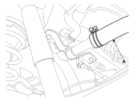
| 10. |
Disconnect the fuel filler hose (A).
|
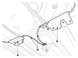
| 11. |
Remove the under cover (A) and the parking brake line installation
bolt (B).
|
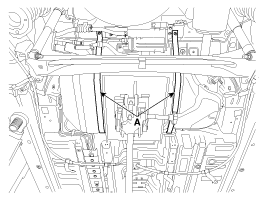
| 12. |
Remove the fuel tank from the vehicle after removing the fuel
tank band (A).
|
Installation
| 1. |
Installation is reverse of removal.
|
 Repair procedures
Fuel Pressure Test
1.
Release the residual pressure in fuel line (Refer to ŌĆ£Release
Residual Pressure in Fuel LineŌĆØ in this group).
...
 Fuel Pump. Repair procedures
Removal
1.
Release the residual pressure in fuel line (Refer to ŌĆ£Release
Residual Pressure in Fuel LineŌĆØ in this group).
2.
Remove th ...
See also:
Seat Heater Switch. Schematic Diagrams
Circuit Diagram
...
Clutch Master Cylinder. Components and Components Location
Components
1. Reverse hose
2. Master cylinder
3. Ignition lock switch
4. Clutch switch
5. Clutch arm assembly
6. Pedal pad
...
Hands Free Switch. Repair procedures
Inspection
1.
Check the hands free remote control switch for resistance between
terminals in each switch position.
Switch
...
Categories
- Hyundai Veloster Manuals Home
- Hyundai Veloster 2010-2017 Owner's Manual
- Hyundai Veloster 2010-2017 Service Manual

┬® 2011-2024 Copyright www.hvmanual.com