
 Hyundai Veloster: Front Disc Brake. Repair procedures
Hyundai Veloster 2011-2017 Service Manual / Brake System / Brake System / Front Disc Brake. Repair procedures
Hyundai Veloster: Front Disc Brake. Repair procedures
Hyundai Veloster 2011-2017 Service Manual / Brake System / Brake System / Front Disc Brake. Repair procedures
Hyundai Veloster 2011-2017 Service Manual / Brake System / Brake System / Front Disc Brake. Repair procedures
Removal
| 1. |
Remove the front wheel & tire.
|
| 2. |
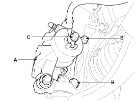
Loosen the hose eyebolt (C) and caliper mounting bolts (B), then
remove the front caliper assembly (A).
|
| 3. |
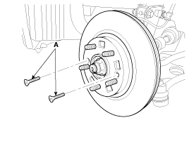
Remove the front brake disc by loosening the screws (A).
|
Replacement
| Front Brake Pads |
| 1. |
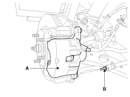
Loosen the guide rod bolt (B) and pivot the caliper (A) up out
of the way.
|
| 2. |
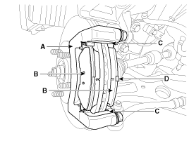
Replace pad shim (D), pad retainers (C) and brake pads (B) in
the caliper carrier (A).
|
Inspection
| Front Brake Disc Thickness Check |
| 1. |
Check the brake pads for wear and fade.
|
| 2. |
Check the brake disc for damage and cracks.
|
| 3. |
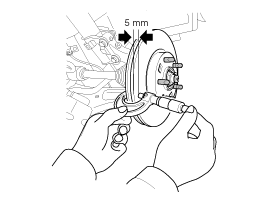
Remove all rust and contamination from the surface, and measure
the disc thickness at 8 points, at least, of same distance (5mm) from
the brake disc outer circle.
|
| 4. |
If wear exceeds the limit, replace the discs and pad assembly
left and right of the vehicle.
|
| Front Brake Pad Check |
| 1. |
Check the pad wear. Measure the pad thickness and replace it,
if it is less than the specified value.
|
| 2. |
Check the damage of pad, backing metal and contamination with
grease.
|
| Front Brake Disc Runout Check |
| 1. |
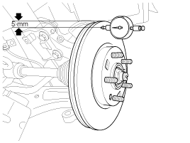
Place a dial gauge about 5mm (0.2 in.) from the outer circumference
of the brake disc, and measure the runout of the disc.
|
| 2. |
If the runout of the brake disc exceeds the limit specification,
replace the disc, and then measure the runout again.
|
| 3. |
If the runout does not exceed the limit specification, install
the brake disc after turning it 180° and then check the runout of the
brake disc again.
|
| 4. |
If the runout cannot be corrected by changing the position of
the brake disc, replace the brake disc.
|
Installation
| 1. |
Installation is the reverse of removal.
|
| 2. |
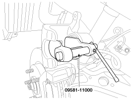
Use a SST (09581-11000) when installing the brake caliper assembly.
|
| 3. |
After installation, bleed the
(Refer to Brake system bleeding)
|
 Front Disc Brake. Components and Components Location
Components
1. Guide rod bolt
2. Bleed screw
3. Caliper body
4. Caliper carrier
5. Inner pad shim
6. Brake pad
7. Pad retainer
...
 Rear Disc Brake. Components and Components Location
Components
1. Guide rod bolt
2. Bleed screw
3. Caliper carrier
4. Caliper body
5. Brake pad
6. Pad retainer
...
See also:
CVVT (Continuously Variable Valve Timing) System. Description and Operation
Description
Continuous Variable Valve Timing (CVVT) system advances or retards the
valve timing of the intake and exhaust valve in accordance with the ECM control
signal which is calculated ...
Power Window Switch. Schematic Diagrams
Circuit Diagram
Driver Power Window Switch
Passenger power window switch
Rear power window switch
...
Tire traction
Tire traction can be reduced if you drive on worn tires, tires that are improperly
inflated or on slippery road surfaces. Tires should be replaced when tread wear
indicators appear. To reduce the ...
Categories
- Hyundai Veloster Manuals Home
- Hyundai Veloster 2010-2017 Owner's Manual
- Hyundai Veloster 2010-2017 Service Manual

© 2011-2026 Copyright www.hvmanual.com