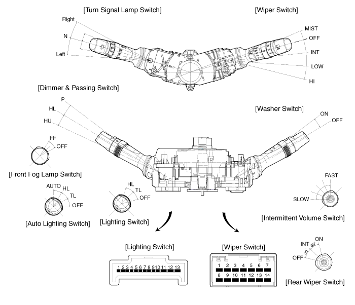
 Hyundai Veloster: Components and Components Location
Hyundai Veloster 2011-2017 Service Manual / Body Electrical System / Multifunction switch / Components and Components Location
Hyundai Veloster 2011-2017 Service Manual / Body Electrical System / Multifunction switch / Components and Components Location
Components(1)

|
Connector name |
No |
Descripton |
Connector name |
No |
RH SIDE |
|
Lighting (13 pin) -LH side |
1 |
Lighting switch ground |
Washer & Wiper (14 pin) -RH side |
1 |
MIST switch |
|
2 |
Tail lamp switch |
2 |
Wiper parking |
||
|
3 |
Auto light switch |
3 |
Wiper low speed |
||
|
4 |
Head lamp switch |
4 |
- |
||
|
5 |
Fog switch base |
5 |
Rear washer switch |
||
|
6 |
Front fog switch |
6 |
IGN2-Rear wiper & washer |
||
|
7 |
- |
7 |
INT rear wiper switch |
||
|
8 |
Head lamp low beam |
8 |
Intermittent wiper switch |
||
|
9 |
Head lamp high beam |
9 |
Wiper high speed |
||
|
10 |
Dimmer switch base |
10 |
ING2-Front washer & wiper |
||
|
11 |
Turn signal left |
11 |
Wahser switch |
||
|
12 |
Turn signal base |
12 |
Intermittent volume base |
||
|
13 |
Turn signal right |
13 |
Intermittent time |
||
|
|
14 |
Rear wiper switch |
|||
 Specifications
Specifications
Items
Specifications
Rated voltage
DC 12V
Operating temperature range
-30°C ~ +80°C (-22 ~ +176°F)
...
 Repair procedures
Inspection
Lighting Switch Inspection
With the multifunction switch in each position, make sure that continuity
exists between the terminals below. If continuity is not as specified, replac ...
See also:
General Information
General Troubleshooting Information
Before Troubleshooting
1.
Check applicable fuses in the appropriate fuse/relay box.
2.
Check the batter ...
Reporting safety defects
If you believe that your vehicle has a defect which could cause a crash or could
cause injury or death, you should immediately inform the National Highway Traffic
Safety Administration (NHTSA) in ...
Normal maintenance schedule
The following maintenance services must be performed to ensure good emission
control and performance. Keep receipts for all vehicle emission services to protect
your warranty. Where both mileage a ...
Categories
- Hyundai Veloster Manuals Home
- Hyundai Veloster 2010-2017 Owner's Manual
- Hyundai Veloster 2010-2017 Service Manual
© 2011-2025 Copyright www.hvmanual.com
